


CrossPoint / MAV Matrix Switchers • Installation
Installation, cont’d
2-4
CrossPoint / MAV Matrix Switchers • Installation
2-5
Refer also to the CrossPoint 450 Plus / MAV Plus User’s Manual at www.extron.com. Refer also to the CrossPoint 450 Plus / MAV Plus User’s Manual at www.extron.com.
e
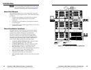
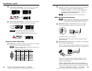
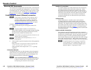
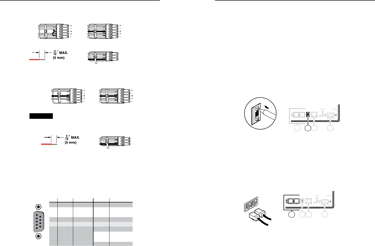
Audio inputs (audio BMEs) — Connect stereo or mono audio
sources to the 5-pole or 3-pole captive screw connectors.
L R
Unbalanced Stereo Input
Balanced Stereo Input
Ring
Sleeve (s)
Tip
Sleeve
Tip
Sleeve
Balanced Mono Input
Tip
Tip
Ring
Ring
Sleeves
Tip
Do not tin the wires!
f
Audio outputs (audio BMEs) — Connect stereo or mono audio
devices to the 5-pole or 3-pole captive screw connectors.
CAUTION For unbalanced stereo audio, connect the
sleeve(s) to the ground contact. DO NOT
connect the sleeve(s) to the negative (-) contacts.
Unbalanced Stereo Output
Balanced Stereo Output
L R
Ring
Tip
Sleeve(s)
Tip
Ring
Sleeve(s)
Tip
Tip
NO GROUND HERE.
NO GROUND HERE.
Balanced Mono Output
Ring
Sleeves
Tip
Do not tin the wires!
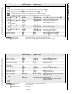
Remote control connections
g
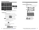
Remote port — If desired, connect a control system or computer
to the rear panel Remote RS-232/RS-422 port.
N
Remote port defaults: RS-232, 9600 baud, no parity, 8-bit,
1 stop bit, no flow control.
RS-232 Function Pin Function
1
2
3
4
5
6
7
8
9
—
TX
RX
—
Gnd
—
—
—
—
Not used
Transmit
Receive
Not used
Ground
Not used
Not used
Not used
Not used
—
TX–
RX–
—
Gnd
—
RX+
TX+
—
Not used
Transmit (–)
Receive (–)
Not used
Ground
Not used
Receive (+)
Transmit (+)
Not used
RS-422
5
1
9
6
h
LAN port — If desired, connect a network WAN or LAN hub, a
control system, or computer to the Ethernet RJ-45 port.
•
Network connection — Wire as a patch (straight) cable.
• Computer or control system connection — Wire the
interface cable as a crossover cable.
N
The factory default IP address is 192.168.254.254.
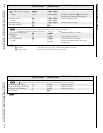
BME connection and selection
N
BME 0 should house the front panel controller (if included
in your system) and be the BME used for system control
and monitoring via the serial and Ethernet LAN ports.
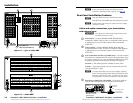
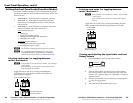
i
BME address switch — Each BME must be set to a unique
address of 0 through 5 (addresses 6 through 9 are invalid).
LAN
ACT
LINK
RESET
REMOTE
Rx
Tx
Rx
Tx
BME COMM
IN OUT
Rx
Tx
4
-
+
BME
ADDRESS
9
8 7
10
Tx
Rx
4
Sync BMEs cannot be set to address 0.
The addresses used in the system must be sequential with no
skipped numbers.
j
BME COMM interconnect ports — The BMEs in multiple BME
systems must be daisy-chained.
Connect an RJ-45 cable from BME 0’s BME Comm Out connector
to the nearest BME’s BME Comm In connector (usually BME 1).
LAN
ACT
LINK
RESET
REMOTE
Rx
Tx
Rx
Tx
4
-
+
BME COMM
IN OUT
BME
ADDRESS
Rx
Tx
9
BME COMM
OUT
IN
From Previous BME
To Next BME
8 7
10
Connect the next RJ-45 cable from BME 1's BME Comm Out
connector to the nearest unconnected BME’s BME Comm In
connector (usually BME 2).
Continue connecting RJ-45 cables from each daisy-chained
module’s BME Comm Out connector to the next module’s BME
Comm In connector until all modules are included in the chain.