


2
MLC 226 IP Series • Setup Guide (Continued)
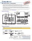
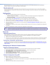
Control — Control Modules, SCP Control Panels (CM/IR/SCP Port)
Bottom
Panel
PR
O
JE
C
T
OR
RS-232/I
R
CM/IR/SCP
A B C D E
T
x/I
R
Rx
G
ROUN
D
PWR SN
S
G
ROUN
D
+12V OU
T
+12V OUT
GROUND
CONT MOD
IR IN
SCP COM
E
D
C
B
A
SCP communication (IR)
Ground ( )
IRCM, ACM, RCM
+12 VDC
C
B
A
Ground ( )
IRCM/ACM/RCM
+12 VDC
DVD & VCR CONTROL
PLAY NEXT/FWDPAUSE STOP
TUNER
Tx
PREV/REW
ENTER
TITLE MENU
TV/VCR
DVD VCR
IRCM-DV+
SCP 226
DISPLAY
SCP 226
1
2
3
4
5
6
VOLUME
CONFIG
IR
ON
OFF
VCR
DVD
DOC
CAM
PIC
MUTE
AUTO
IMAGE
MUTE
LAPTOP
PC
CM/IR/SCP Port
• SCPs: Two maximum per system
• Control modules: four maximum (four module addresses)
• Total distance from port to last device: 200 feet (61 m) maximum
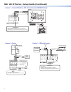
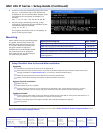
Control — Relay
NORMALLY OPEN
RS-232 12
V
1 2
COMMON
COMMON
COMMON
G
ROUN
D
G
ROUN
D
G
ROUN
D
A
RELAYS
IR/SERIAL OUT
ML
S
PWR
3 4
B
5 6
C
S
A
S
B
L
L
A
B
S
C
Rx
Tx
G
ROUND
G
ROUND
+12V IN
Relay 6
Relay 5
Common
Room
Control
Equipment
Normally
Open (5)
Common
Normally
Open (6)
Common
All relays are
normally open.
Relays
• Connect devices for contact control.
• Do not exceed a total of 24 VDC at 1 A for each port.
Bottom
Panel
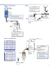
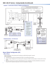
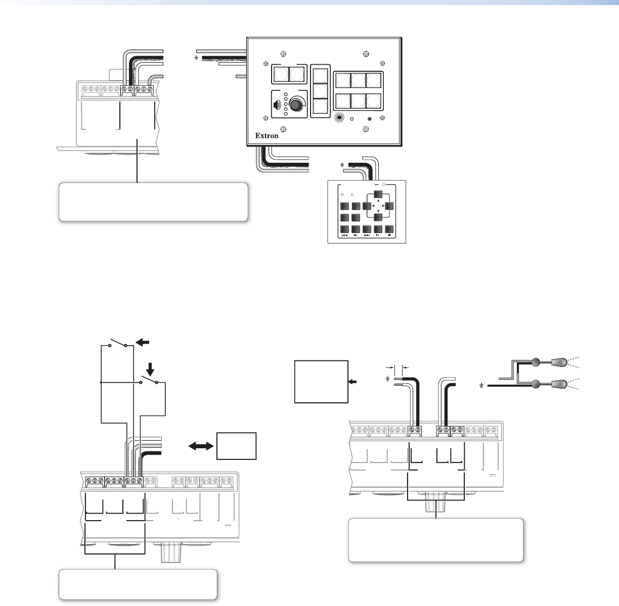
Control — IR/Serial Output
NORMALLY OPE
N
RS-232 12
V
1
2
C
OMMO
N
C
OMMO
N
C
OMMO
N
GROUND
GROUND
GROUND
A
RELAY
S
IR/SERIAL OUT
M
LS
PWR
3
4
B
5
6
C
S
A
S
B
A
B
S
C
Rx
T
x
G
R
OU
ND
G
R
OU
ND
+12V IN
(+)
(-)
(+)
(-)
(-)
(+)
Two Single IR Emitters
Ground ( )
IR Output Signal
Unidirectional
IR
IR or RS-232
Output
Ground
( )
Strip wires
3/16"
(5 mm)
max.
Wired IR Remote
or RS-232 Port
on Projector,
Panel Display, or
Source Device
Bottom Panel
IR/Serial Ports
Output options:
• IR (with or without carrier signals, 0 to +5 VDC)
• unidirectional RS-232 (-5 to +5 VDC; default protocol:
9600 baud, no parity, 8 data bits, 1 stop bit, no flow control