


4
MLC 226 IP Series • Setup Guide (Continued)
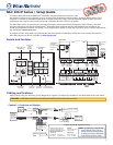
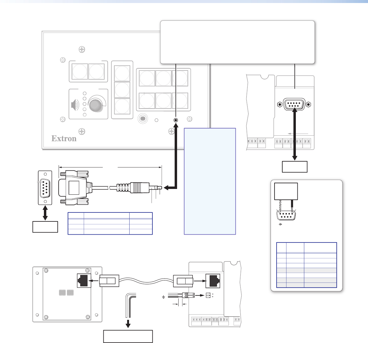
Control — Serial (Host Control, Cong) and Digital I/O
Communication — IP Intercom
R
INTERCOM
AUDIO
OUT
Audio Signal (Tip, +)
Ground (Sleeve, )
Speaker, Audio System,
or Paging System
0.2" (5 mm)
Max.
IPI 104 AAP IP Intercom
®
Rear Panel
MLC 226 IP Series
Rear Panel (left side)
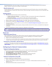
About Global Congurator (GC)
What It Does
Global Configurator is the software tool for setting up an MLC and the system it controls.
Global Configurator:
z Loads device drivers and uses commands from them for controlling other products
z Creates a single configuration file containing all the settings for the MLC and the products it interacts with in the AV
system
z Generates a graphical user interface called GlobalViewer that is uploaded to the MLC (a GlobalViewer host device)
along with the completed configuration and can be accessed as a web page
DI
S
PLA
Y
ML
C
22
6
I
P
1
2
3
4
5
6
V
O
L
U
M
E
CONFIG
IR
ON
O
F
F
V
CR
DVD
LAPTOP
P
LAPTOP
PC
SCREEN
S
N
SCREEN
DO
W
N
A
U
T
O
I
MA
G
E
SCREEN
S
N
SCREEN
U
P
AUX
VIDEO
DOC
C
A
M
HOST
CONTROL
1=DIGITAL I/O
2=Tx 3=Rx 5=GND
38400, N, 8, 1
PRE
SS
TAB WITH
T
WEEKER TO REMOVE
LAN
6 feet
(1.8 m)
Part #70-335-01
5
1
9
6
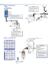
Sleeve (Gnd)
Ring
Tip
9-pin D Connection TRS Plug
Pin 2 Computer Rx line Tip
Pin 3 Computer Tx line Ring
Pin 5 Computer signal ground Sleeve
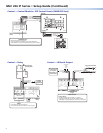
Front Panel
Rear Panel
RS-232 Port
on a PC
RS-232 Port
on a PC
These ports support bidirectional RS-232 (-5 - +5 VDC) communication.
Both ports serve the same RS-232 function, but operate independently of each other.
Protocol:
• 38400 baud • 8 data bits • 1 stop bit • no parity • no flow control
Host Control and Config Serial (RS-232) Ports
Front panel Config port:
• RS-232 only (Tx, Rx, ground)
Rear panel Host Control port:
• RS-232 and digital I/O
RS-232
Pin
Function
Description
1 Digital I/O Digital input/output
2 Tx Transmit data
3 Rx Receive data
4 – No connection
5 Gnd Signal ground
6, 7 – No connection
8, 9 – No connection
Host Config Port
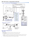
Digital I/O
Pins 1 and 5 of this
port can be used as a
digital input or output,
with or without
+5 VDC pull-up.
Once configured, the
digital input or output
can monitor or trigger
events and functions
(toggle relays, issue
commands, send
e-mail).
Pin 1
Pin 5 ( )
15
Switch,
Sensor,
Relay
NOTES:
• Use the front panel
Config port and
rear panel Host
Control ports only
for sending basic
SIS commands (such
as those for IP
setup and
troubleshooting)
and checking unit
information and
responses.
• You must use the
LAN port (not the
Config or Host
port) to set up the
MLC and upload
GC configuration
files or firmware.