


3
Control — MLS Switcher
12VRS-232
GROUND
GROUND
GROUND
IR/SERIAL OUT
MLS PWR
A
S
B
AB
S
C
Rx
Tx
GROUND
GROUND
+12V IN
1
2
V
GROUND
G
ROUN
D
G
ROUN
D
IR/SERIAL OUT
P
W
R
A
S
B
L
L
S
C
G
ROUN
D
+
12V IN
Ground ( )
Transmit (Tx)
B
Receive (Rx)
A
Transmit (Tx)
Receive (Rx)
B
A
MLC/IR
ABC
Rear Panel
MLC/IR port
on MLS Switcher
Heat Shrink
Over Ground
or Drain Wires
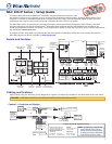
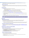
Select RS-232 protocol via software or SIS
command. Signals are bidirectional, ±5 V.
RS-232 default protocol:
• 9600 baud • 8 data bits • 1 stop bit
• no parity • no flow control
NOTES:
• You must connect a ground wire
between the MLC and MLS.
• If you use cable that has a drain wire,
tie the drain wire to ground at both ends.
MLS Switcher RS-232 Port
MLC
Bottom
Panel
Power
12VRS-232
GROUND
GROUND
I
R/SERIAL OUT
MLS PWR
S
B
AB
S
C
Rx
Tx
GROUND
GROUND
+12V IN
RS-23
2
G
ROUND
G
ROUND
IR/SERIAL OUT
ML
S
S
B
L
L
A
B
S
C
R
x
T
x
G
ROUND
Ground ( )
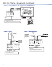
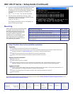
+12 VDC Input
Ground all devices.
External
Power Supply
(12 VDC, 1 A max.)
Ground
(ridged)
12 VDC
(smooth)
Bottom
Panel
3/16"
(5 mm)
Max.
Power Input
• Connect to 12 VDC, 1 A power supply.
• Check the polarity of the power supply
wires before connecting it to the MLC.
• Front panel buttons light when the
MLC receives power.
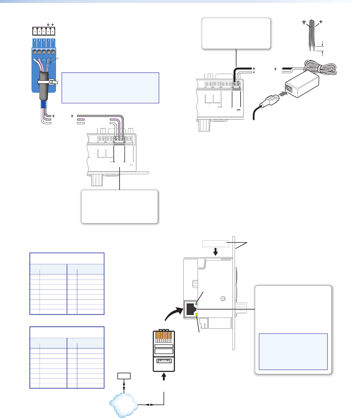
Control — LAN (Ethernet)
MAC: 00-05-A6-XX-XX-XX
S/N:
Left Panel
RJ-45
Connector
Insert Twisted
Pair Wires
Pins:
12345678
Link LED:
Lights to
indicate
a network
connection.
Activity LED:
Blinks to indicate
data is being sent
or received.
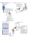
Ethernet (LAN)
Connect to an Ethernet network with a
straight through cable. This port must be
configured.
Default protocol:
• MLC IP address: 192.168.254.254
• Gateway IP address: 0.0.0.0
• Subnet mask: 255.255.0.0
• DHCP: off
• Link speed and duplex level: autodetected
MAC Address
(on top, and on front panel)
Straight-through Cable
(for connection to a switch, hub, or router)
End 1 End 2
Pin Wire Color Pin Wire Color
1 white-orange 1 white-orange
2 orange 2 orange
3 white-green 3 white-green
4 blue 4 blue
5 white-blue 5 white-blue
6 green 6 green
7 white-brown 7 white-brown
8 brown 8 brown
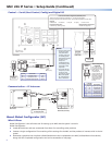
Crossover Cable
(for direct connection to a PC)
End 1 End 2
Pin Wire Color Pin Wire Color
1 white-orange 1 white-green
2 orange 2 green
3 white-green 3 white-orange
4 blue 4 blue
5 white-blue 5 white-blue
6 green 6 orange
7 white-brown 7 white-brown
8 brown 8 brown
PC
TCP/IP
Network
NOTE:
You must use this
LAN port to set up the MLC
and upload GC configuration
files and firmware.
All configuration can be
performed via this port.
Both ends use the TIA/EIA T568A wiring standard.
Wire end 1 following the TIA/EIA T568A wiring standard,
wire end 2 with the T568B wiring standard.