


MediaLink
™
VersaTools
©
Switchers • Installation
MediaLink
™
VersaTools
©
Switchers • Installation
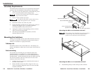
Installation, cont’d
For dBV the reference is 1 volt.
For dBu the reference is 0.775 volts.
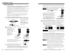
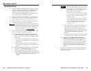
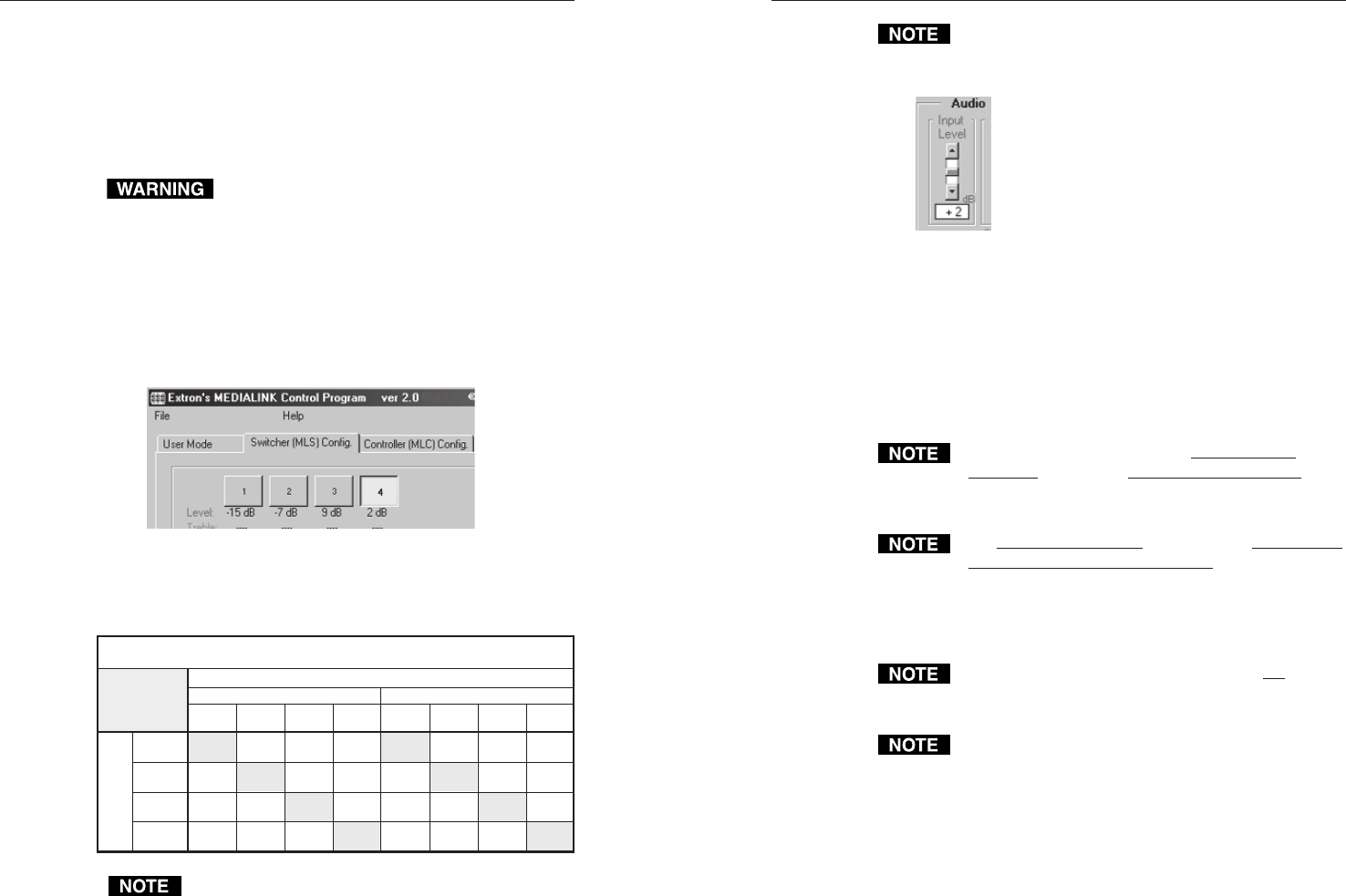
5. In the control program, move the Audio Input Level slider
to select the gain/attenuation for that input,
as shown at left.
6. Repeat steps 3–5 for the other three inputs.
7. Test the system by listening to audio output for each input.
Start by setting the audio output to the lowest level.
7a. If the audio output is too loud or is clipping
(becoming distorted as the loudest parts are cut off),
decrease the gain for that input.
7b. If the output is too soft or inaudible, increase the gain.
Input gain and attenuation for audio inputs 1
through 4 is adjustable via RS-232 control only
(using SIS commands or the MediaLink Control/
Configuration Software.)
The Aux/Mix input level can be adjusted via the front
panel Aux/Mix Level control only. Aux/Mix level
can not be adjusted via RS-232 (SIS commands,
configuration software, or an MLC MediaLink
Controller). The Aux/Mix level is independent of the
input and volume controls for the four switchable inputs.
Volume for the four switchable inputs is not
adjustable via the front panel. It can be adjusted only via
RS-232 (including via an MLC).
Wait at least ten (10) seconds between making a change
(input selection or audio adjustment) and disconnecting
power from the MLS. The switcher needs several
seconds to store and save the new settings in its memory.
2-11
HyperTerminal, a third party controller, or the MediaLink
Control/Configuration Software). The gain and attenuation for
the Aux/Mix input are adjustable only via the switcher’s front
panel. (See page 3-3 for Aux/Mix details.)
Setup via the MediaLink
™
Control/Configuration
Software
To avoid damage to your hearing, the output
volume should be set as low as possible before you
test the sound system.
1. Cable and power on all the equipment.
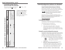
2. Start the MediaLink Control Software (see page 4-7), and
select the Switcher (MLS) Config portion of the program
(the second tab from the left).
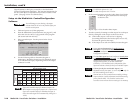
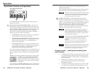
3. Select an audio input. See the picture below for an
example.
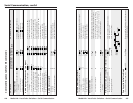
4. Use the following table to determine the gain or
attenuation. Match the desired level for balanced output
or for unbalanced output, depending on how the output
connector is wired.
Gain and Attenuation Settings for MLS 100 Series Switchers
Desired Output Levels
Balanced
+4 dBu 0 dB -4 dB -12 dB -22 dB
0 dB
0 dB
0 dB
+6 dB
+4 dB -8 dB -18 dB
+8 dB+12 dB
10 dB+18 dB+22 dB
-10 dB
+10 dB +6 dB
+6 dB
+6 dB
+2 dB -6 dB -16 dB
-2 dB -12 dB
+18 dB +14 dB
+16 dBn.a. +24 dB
-4 dB
+4 dBu
0 dBu
0 dBu
-10 dBV
(-8 dBu)
-10 dBV
(-8 dBu)
-20 dBV
(-18 dBu)
-20 dBV
(-18 dBu)
+4 dBu 0 dBu
-10 dBV
(-8 dBu)
-20 dBV
(-18 dBu)
Input Source
Levels
Unbalanced
If you wire an audio output for balanced output, the
MLS outputs a unity signal (input level = output level).
If you wire an audio output for unbalanced output, it
causes the audio signal to be attenuated by 6 dB (gain =
-6 dB).
2-10