


MediaLink Switchers • Serial Communication4-2
Serial Communication
The MediaLink switcher can be remotely set up and controlled via a host computer
or other device (such as a control system) attached to the rear panel RS-232/
Contact Closure port. Alternatively, the switcher can be controlled by an optional
MediaLink Controller (MLC 206) (connected to the MLS’s MLC/IR port) or by an
RS-232 device acting through the MLC. The control device (host) can use either
Extron’s Simple Instruction Set (SIS) commands or the graphical control program
for Windows. For details on use and setup of a system that includes a MediaLink
Controller, see the MediaLink Controller User’s Manual.
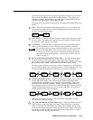
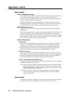
The switcher uses a protocol of 9600 baud, 1 stop bit, no parity, and no flow control.
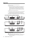
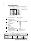
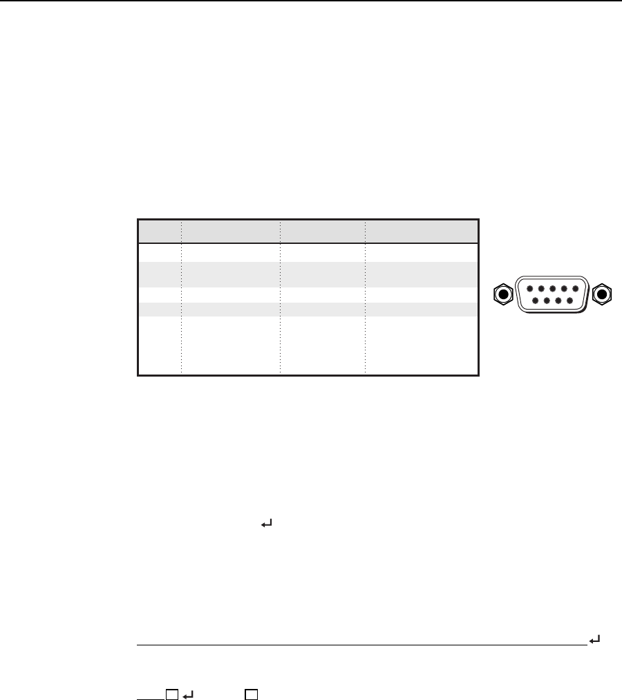
The rear panel RS-232 9-pin D connector has the following pin assignments:
Pin
RS-232
function
Description
Contact closure
1 – Input 1 Input 1
2 Tx Transmit data –
3 Rx Receive data –
4 – Input 2 Input 2
5 Gnd Signal ground –
6 – Input 3 Input 3
7 – Input 4 Input 4
8 – Input 5 Input 5
9– Input 6 Input 6
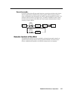
DB9 Pin Locations
Female
51
96
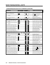
RS-232 Programmer’s Guide
Host-to-MLS communications
SIS commands consist of one or more characters per field. No special characters
are required to begin or end a command sequence. When the MLS determines that
a command is valid, it executes the command and sends a response to the host
device. All responses from the switcher to the host end with a carriage return and
a line feed (CR/LF = ), which signals the end of the response character string. A
string is one or more characters.
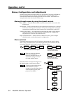
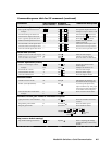
MLS-initiated messages
When a local event such as a front panel selection or adjustment takes place, the
MLS responds by sending a message to the host. No response is required from the
host. The MLS-initiated messages are listed here (underlined).
(c)Copyright 2001, Extron Electronics, MediaLink Switcher MLS506SA, Vx.xx
The MLS sends the copyright message when it first powers on. Vx.xx is the
firmware version number. The MLS 506SA is used in this example.
C hn
X1
(where
X1
is the input number)
The MLS sends this response when an input is switched.
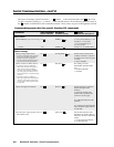
Error responses
When the MLS receives a valid SIS command, it executes the command and sends a
response to the host device. If the MLS is unable to execute the command because
the command is invalid or it contains invalid parameters, it returns an error
response to the host.
The error response codes and their descriptions are as follows:
E01 – Invalid input channel number (the number is too large)
E10 – Invalid command
E13 – Invalid value (the number is out of range/too large)
E14 – Invalid for this configuration.