


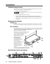
Installation, cont’d
MediaLink Switchers • Installation2-6
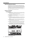
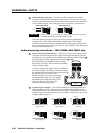
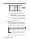
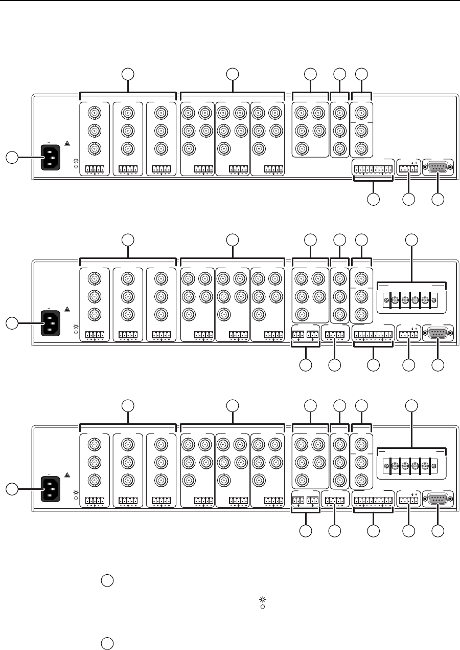
MLS 506, MLS 506MA, and MLS 506SA
Rear Panels and Cabling
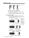
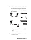
Power connection
1
AC power connector and power indicator LED — Plug a standard IEC power
cord into this connector to connect the switcher to a 100 to 240VAC, 50 Hz or
60 Hz power source. The LED ( ) lights while the MLS is receiving power.
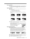
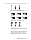
Input connections
2
Inputs 1–3 — For inputs 1, 2, and 3, connect cables from the video sources to
the MLS’s input BNC connectors according to the video format as shown in
the following illustration. You must also select between “Vid” (for composite
video or S-video) and “YUV” (for component video) in the LCD menu or via
the Windows-based setup program. See pages 3-5, 3-6, and 4-9.
100-240V 0.2A 50/60 Hz
.5A MAX
INPUT 1
VIDEO
Y
C
R-Y
B-Y
YUV
Y
R-Y
B-Y
VIDEO
S-VIDEO
Y
C
INPUT 2
VIDEO
Y
C
R-Y
B-Y
INPUT 3
VIDEO
Y
C
R-Y
B-Y
INPUT 4
RH/
HV
G
V
B
INPUT 5
RH/
HV
G
V
B
INPUT 6
RH/
HV
G
V
B
RGB
RH/
HV
G
V
B
4 ohm
MONO AMPLIFIED OUTPUT
COMM 8 ohm 70V
LR LR LR
LR
AUX/MIXEFFECTS
LR
SEND
LR
RETURN
MLC/IR RS232
CONTACT CLOSURE
ABC
AUDIO OUT
FIXEDVARIABLE
LRLR
L LRR LR
100-240V 0.2A 50/60 Hz
.5A MAX
INPUT 1
VIDEO
Y
C
R-Y
B-Y
YUV
Y
R-Y
B-Y
VIDEO
S-VIDEO
Y
C
INPUT 2
VIDEO
Y
C
R-Y
B-Y
INPUT 3
VIDEO
Y
C
R-Y
B-Y
INPUT 4
RH/
HV
G
V
B
INPUT 5
RH/
HV
G
V
B
INPUT 6
RH/
HV
G
V
B
RGB
RH/
HV
G
V
B
LR LR LR
MLC/IR RS232
CONTACT CLOSURE
ABC
AUDIO OUT
FIXEDVARIABLE
LRLR
L LRR LR
100-240V 0.2A 50/60 Hz
.5A MAX
INPUT 1
VIDEO
Y
C
R-Y
B-Y
LR LR LR LR LR LR
LR
YUV
Y
R-Y
B-Y
VIDEO
S-VIDEO
Y
C
INPUT 2
VIDEO
Y
C
R-Y
B-Y
INPUT 3
VIDEO
Y
C
R-Y
B-Y
INPUT 4
RH/
HV
G
V
B
INPUT 5
RH/
HV
G
V
B
INPUT 6
RH/
HV
G
V
B
RGB
RH/
HV
G
V
B
AUX/MIXEFFECTS
LR
SEND
LR
RETURN
MLC/IR RS232
CONTACT CLOSURE
STEREO AMPLIFIED OUTPUT
LEFT RIGHT
ABC
AUDIO OUT
FIXEDVARIABLE
LRLR
1
2 3 4 5 6 7
9 11
11
11
10 12 13
1
2 3 4 5 6 8
9 10 12 13
1
2 3 4 5 6
12 13
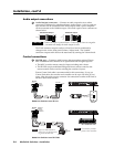
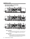
MLS 506 Rear Panel
MLS 506 MA Rear Panel
MLS 506 SA Rear Panel