


2-13MediaLink Switchers • Installation
2. Remove the switcher from the rack, or furniture and set it on a level, stable
surface.
3. Remove the cover of the switcher (the top half of the enclosure) by removing
the screws, then lifting the cover straight up. Set the cover down on a level
surface, and save the screws for later use.
CAUTION
Do not touch any switches or other electronic components inside the
switcher. Doing so could damage the switcher. Electrostatic discharge
(ESD) can damage IC chips even though you cannot feel it. You must be
electrically grounded before proceeding with jumper installation or
replacement. A grounding wrist strap is recommended.
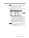
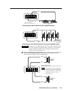
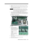
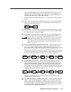
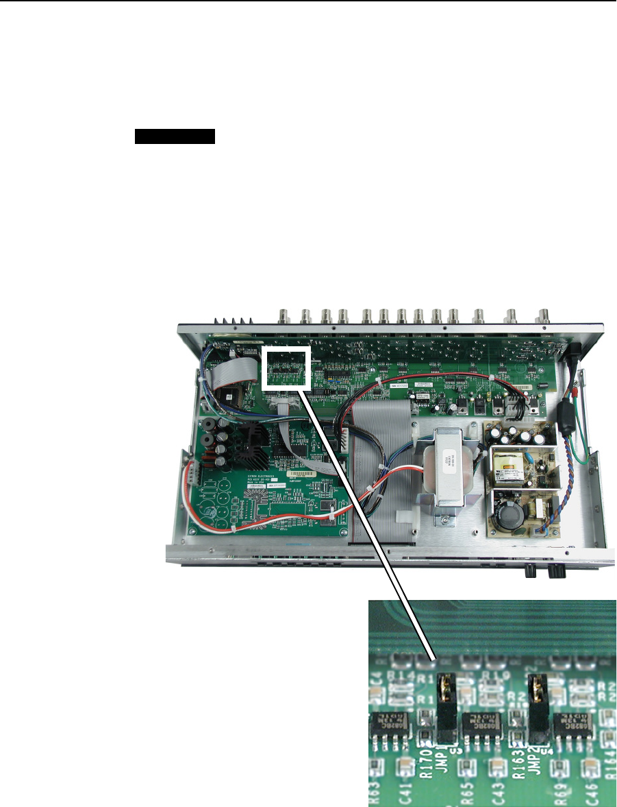
4. Locate the pairs of pins labeled JMP1 and JMP2 on the circuit board, as
shown in the boxed area of the following picture, which shows the pins with
the jumpers already set for the -6dB attenuation. The MLS 506MA is shown in
the example below, but these jumpers are in the same location in all models.
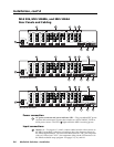
MLS 506MA Rear Panel (Top View)
MLS 506MA Front Panel
(Top View)
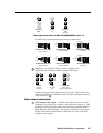
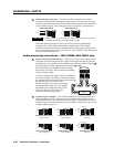
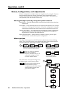
5. After you are electrically
grounded, place a jumper on
the pins for the audio channel to
which the -6dB attenuation will
be applied, or remove a jumper
to remove the attenuation.
• JMP1 is for the left audio
channel.
• JMP2 is for the right audio
channel.
The picture at right shows
jumpers set for both left and
right channels.
JMP1 and JMP2 -6dB Audio Jumpers
6. Replace the top cover on the switcher, and fasten it with the screws that were
removed in step 3.
7. Rack mount the switcher or mount it into the furniture.
8. Reconnect the AC power cord.