


3
2002 - INLINE, INC. MSX1616 OPERATION MANUAL - v1.0 5/8/02
MSX1616 Matrix Switcher - Quick Start
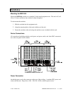
Installation
Step 1
Install the switcher into a standard 19"
equipment rack, or set it on a flat surface.
Step 2
Connect input video sources to the BNC
connector inputs. Connect sync inputs to the
H/C and V connectors and video inputs to
the RGB connectors.
Step 3
Connect output devices (monitors, data
projectors, etc.) to the BNC outputs.
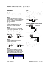
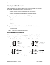
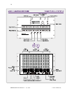
Step 4
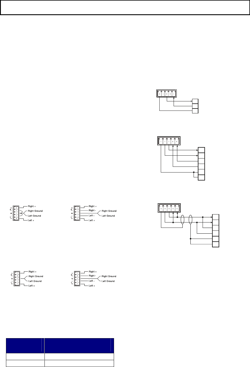
Connect audio sources to the audio inputs
(5-pin captive screw terminals). The wiring
diagram below illustrates connections for
unbalanced and balanced audio signals.
For unbalanced Stereo
Audio Input:
For balanced Stereo
Audio Input:
Step 5
Connect the audio outputs to the audio
system’s line level input.
For unbalanced
Stereo Audio Output:
For balanced Stereo
Audio Output:
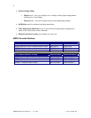
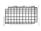
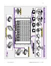
Step 6
Select the serial communication protocol
format for serial port 1 as required by the
control system. Set DIP switches in Switch
Bank 1 according to the following chart:
Port 1 Serial
Format:
Switch 1 DIP Switch
Settings:
RS-232 Set switches 123 to OFF
RS-422/485 Set switches 123 to ON
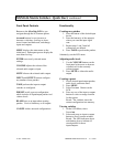
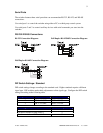
Step 7
If you will be controlling the switcher with
serial commands, cable the control system
or computer serial port to serial port 1 based
on the type of connection described below.
RS-232 Connection Diagram:
MSV0804
Serial Port
Computer Serial Port
(DB-9 Connector)
GND
TX-
TX+
RX-
RX+
2
3
5
RX
TX
GND
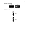
Full Duplex RS-422/485 Connection Diagram:
MSV0804
Serial Port
Computer Serial Port
(DB-9 Connector)
GND
TX-
TX+
RX-
RX+
RX+
RX-
TX+
TX-
GND
GND
3
7
2
6
5
1
Half Duplex RS-485 Connection Diagram:
MSV0804
Serial Port
Computer Serial Port
(DB-9 Connector)
GND
TX-
TX+
RX-
RX+
RX+
RX-
TX+
TX-
GND
GND
3
7
2
6
5
1
Step 8
Connect power and turn on the switcher,
display devices, control, and audio
equipment as applicable.