


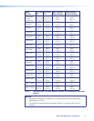
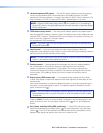
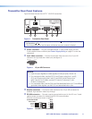
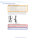
d Vertical frequency DIP switch — The first DIP switch selects the vertical frequency
for the pre-programmed EDID. When switched to Off (default position), the EDID
selected by the rotary positions 1 through E are based on 60 Hz. When switched to On,
they are based on 50 Hz. The second DIP switch, marked Spare, is not used.
NOTE: When the EDID select rotary switch (
e
) is in position 0 or F, the setting of
the first DIP switch is not applicable because the user-recorded or attached display
EDID is being used.
e EDID select rotary switch — The rotary switch selects specific pre-programmed or
user-recorded EDID settings. Position 0 of this 16 position rotary switch selects the user
recorded EDID. Position F passes the EDID from the display connected to the loop-out
back to the input. Positions 1 through E select
pre-programmed EDID resolutions.
NOTE: The refresh rate of the pre-programmed EDID resolutions is selected using
the first DIP switch (
d
).
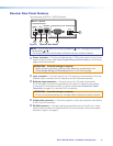
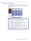
f
Level control — The level control alters the video output voltage to affect the
brightness of the displayed image. Adjust the knob while viewing the displayed image to
set the level that provides the best picture quality.
NOTE: For best results when using an RL receiver, connect a load to the buffered
output on the receiver before adjusting the level.
g
Peaking control — Peaking affects the sharpness of a picture. Increased peaking
can compensate for mid and high frequency detail loss from low bandwidth
system components or capacitance in long cables. The minimum setting (at the
counterclockwise limit) provides no peaking. The maximum setting (at the clockwise
limit) provides 100% peaking. Adjust this control to obtain the optimum picture
sharpness.
h
Select button (SEQ model only) — This recessed button selects the Red, Green,
or Blue video signal to adjust and resets all three video signals to a skew delay of zero
nanoseconds.
Use a small screwdriver to press and release this button to cycle among selecting the
red, green, or blue video signal to adjust. The selected signal is indicated by the red,
green, and blue LEDs (
i
).
NOTE: The SEQ receiver automatically saves the setting for the video signal that is
being deselected when you push this button or when the selection times out after
10 seconds.
Press and hold this button for approximately 3 seconds to set the skew delay for red,
green, and blue to zero. The red, green, and blue LEDs (
i
) all turn off. Release the
button.
i
Red, Green, and Blue LEDs (SEQ model only) — These LEDs indicate the video
signal that is selected by the Select button (
h
) for skew adjustment using the Delay
control (
j
). The LED of the selected color flashes when skew compensation for the
selected video signal has reached the minimum or maximum limit.
MTP 15HD RS Series • Installation and Operation 7