


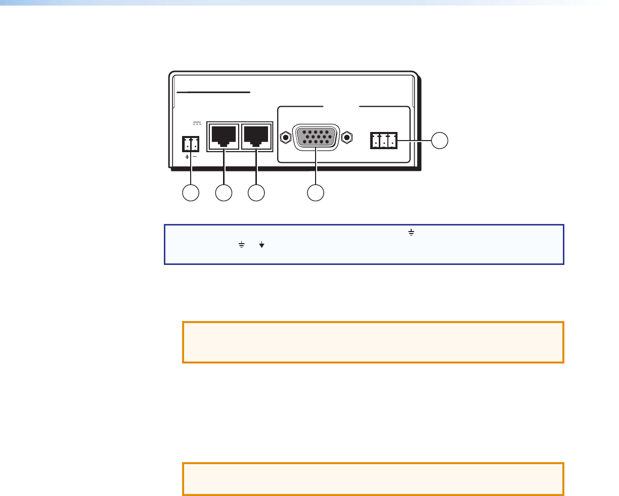
Receiver Rear Panel Features
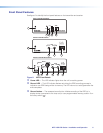
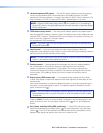
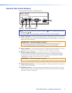
Figure 6 shows an MTP RL 15HD RS receiver.
INPUT
BUFFERED
OUTPUT
OUTPUT
POWER
12V
0.5A MAX
MTP RL 15HD RS
RS-232
RxTx
OUTPUTS
G
1
2 3 4
3
Figure 6. Receiver Rear Panel
NOTE: Control signal ground pins may be labeled as or “G”. Audio ground pins may
be labeled as or .
The wiring and function are the same, whichever way your product is labeled.
a
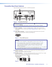
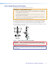
Power connector — Plug the included external 12 VDC power supply into this 2-pole
captive screw connector (see Power Supply Wiring and Grounding on the following
page to wire the connector).
ATTENTION: Potential damage to property.
Before wiring the connector, read the notes, attentions, and warnings in the
Power Supply Wiring and Grounding section on the following page.
b
Input connector — Connect one end of the TP cable from the transmitter or from the
buffered output connector of an RL receiver to this RJ-45 female connector.
c
Buffered output connector — Connect one end of a TP cable to this female
RJ-45 connector. Connect the opposite end of the same TP cable from the receiver
to the Input RJ-45 female connector on another receiver (see Twisted Pair Cable
Termination on page 14 to wire the RJ-45 connectors).
ATTENTION: Potential damage to property.
Do not connect these devices to a computer data or telecommunications network.
d
Output video connector — Connect a projector or other high resolution video device
to this 15-pin HD connector.
e
RS-232 connector — Connect a serial communications port to this 3.5 mm, 3-pole
captive screw connector for bidirectional RS-232 communication. Wire the connector
as shown in figure 5 on page 9.
MTP 15HD RS Series • Installation and Operation 11