


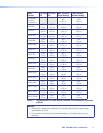
Transmitter Rear Panel Features
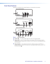
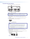
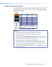
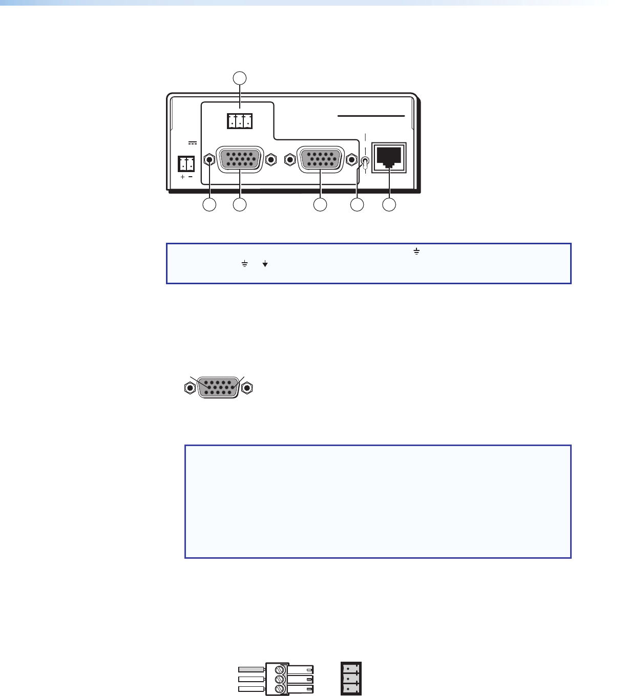
Figure 3 shows the rear of an MTP T 15HD RS transmitter.
OUTPUT
INPUT
POWER
12V
0.5A MAX
Tx Rx G
RS-232
MONITOR
PRE-PEAK
ON
OFF
MTP T 15HD RS
1 2
3 6
4
5
Figure 3. Transmitter Rear Panel
NOTE: Control signal ground pins may be labeled as or “G”. Audio ground pins may
be labeled as or .
The wiring and function are the same, whichever way your product is labeled.
a
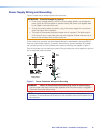
Power connector — Plug the included external 12 VDC power supply into this
2-pole captive screw connector (see Power Supply Wiring on page 12 to wire the
connector).
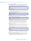
b
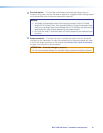
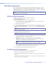
Input video connector — Connect a computer video source to this 15-pin HD
connector for high resolution video input (see figure 4).
51
15 11
610
Female
Figure 4. 15-pin HD Connector
NOTES:
• Input only sync signals (no video signals) on the sync pins (13 and 14).
• For component video, use the R (R-Y) and R return pins (pins 1 and 6),
G (Y) and G return pins (pins 2 and 7), and B (B-Y) and B return pins
(pins 3 and 8). For S-video, use the R, R return (C-chroma), G, and
G return (Y-luma) pins.
• For composite video, use the G pin and the associated return pin. For additional
genlocked video signals, use the R, B, and associated return pins.
c
Monitor connector — Connect a video monitor to this 15-pin HD connector for
buffered, high resolution video loop-through.
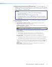
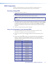
d
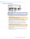
RS-232 connector — Connect a serial communications port to this 3.5 mm, 3-pole
captive screw connector for bidirectional RS-232 communication.
Wire the connector as shown in figure 5.
Ground
Tx
Rx
G
Receive
Transmit
Connected RS-232
Device Pins
MTP
Pins
Figure 5. RS-232 Connector Wiring
MTP 15HD RS Series • Installation and Operation 9