


VersaTools
®
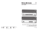
MTP DA4 and MTP DA8 • InstallationVersaTools
®
MTP DA4 and MTP DA8 • TP Cable Advantages
VersaTools
®
MTP DA4 and MTP DA8, cont’d
VersaTools
®
MTP DA4 and MTP DA8 • ConnectionsVersaTools
®
MTP DA4 and MTP DA8 • Connections10
4
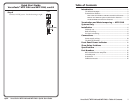
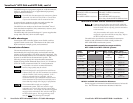
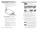
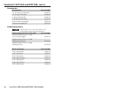
Output Mute connections — The Output Mute connector
provides a way to mute (blank) any or all TP outputs. Each
numbered pin of the captive screw connector is assigned to one
of the DA’s outputs (pin A is assigned to all DA outputs)
(figure 7). When you short and latch a numbered pin or pins to
ground, the DA mutes the associated output(s).
Out #3
Pin Contact closure Function
1 Out #1 Mute output #1
2 Out #2 Mute output #2
3 Mute output #3
4 Out #4 Mute output #4
5 Out #5 Mute output #5
6 Out #6
Out #7
Out #8
Out All
Mute output #6
Mute all outputs
Mute output #7
Mute output #8
7
8
A
Gnd Ground
1234 5678A
MTP DA8
Output Mute Connector
1234A
MTP DA4
Output Mute Connector
Figure 7 — Mute connector and pinout
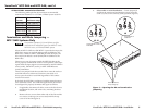
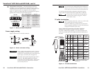
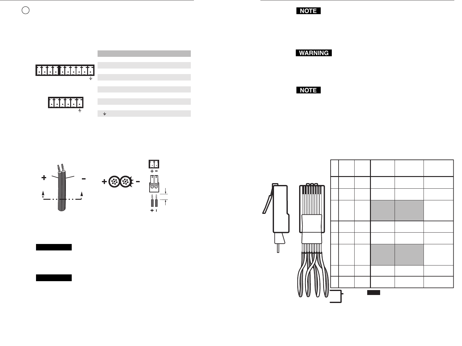
Power supply wiring
Figure 8 shows how to wire the connector.
Power Supply
Output Cord
Captive Screw
Connector
0.2” (5 mm)
SECTION A–A
Ridges
Smooth
AA
Figure 8 — Power connector wiring
CAUTION
Power supply voltage polarity is critical. Incorrect
voltage polarity can damage the power supply and
the MTP DA. Identify the power cord negative lead
by the ridges on the side of the cord (figure 8).
CAUTION
The length of the exposed (stripped) copper wires is
important. The ideal length is 0.2" (5 mm).
Longer bare wires can short together. Shorter wires
are not as secure in the captive screw connectors
and could be pulled out.
Do not tin the power supply leads before installing the
captive screw connector. Tinned wires are not as secure
in the captive screw connectors and could be pulled out.
To verify the polarity before connection, plug in the power
supply with no load and check the output with a voltmeter.
The two power cord wires must be kept separate
while the power supply is plugged in. Remove
power before wiring.
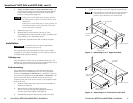
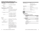
TP cable termination
RJ-45 termination with CAT 5, CAT 5e, or CAT 6 cable
must comply with the TIA/EIA T 568A or
TIA/EIA T 568B wiring standards for all connections.
RJ-45 termination with Skew-Free A/V UTP cable must
comply with TIA/EIA T 568 A only.
Figure 9 details the termination of TP cables with RJ-45
connectors in accordance with the TIA/EIA T 568A or
TIA/EIA T 568B wiring standards. Use either standard with
CAT 5/5e/6 cable, but use the same standard on both ends of
the cable.
Pin
1
Video +
2 Video –
3
4
Audio
left +
5
Audio
left –
6
7
Audio
right +
8
Audio
right –
Wire
color
White-
green
Green
White-
orange
Blue
White-
blue
Orange
White-
brown
Brown
Wire
color
568 A 568 B
Composite
video
MTP signal
White-
orange
Orange
White-
green
Blue
White-
blue
Green
White-
brown
Brown
Clip Down
RJ-45 Connector
Side
1
1&2
3&6 4&5
7&8
2345678
1Pins 2345678
Twisted
Pairs
NOTE
If you are using Enhanced Skew-Free™
A/V cable, use the TIA/EIA T 568A
standard only.
Luma (Y) +
Luma (Y) –
Chroma (C) &
audio left +
Chroma (C) &
audio left –
Audio right+
Audio right –
S-video
MTP
signal
Red/
V. Sync +
Red/
V. Sync –
Mono audio +
or RS-232 +
(MTP 15HD
only)
Green +
Green –
Mono audio –
or RS-232 –
(MTP 15HD
only)
Blue/
H. Sync +
Blue
H. Sync –
RGB video
MTP, VTT/VTR
signal
Figure 9 — TP cable termination
11