


Refer also to the MTPX User’s Manual at www.extron.com.
Refer also to the MTPX User’s Manual at www.extron.com.
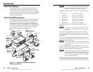
Outputs
e
TP outputs — Connect up to 8, 16, or 32 (depending
on the matrix size) compatible MTP receivers to the
Outputs RJ-45 connectors.
f
Local RGB (VGA) outputs — Connect one
or two RGBHV video displays to the Local
Outputs (VGA) 15-pin HD female connectors.
N
These outputs are always outputs 1 and 2.
N
The video that is output on this (these) connector(s) is
converted from the tied proprietary TP input signal or the
local (VGA) input.
N
This connector can also output HD component video,
component video, S-video, or composite video if that is the
video format that was input.
If the video output is NTSC component video, S-video, or
composite video, set the output to turn off sync stripping.
See the Local video output sync polarity
SIS commands on page 4-5.
g
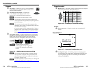
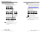
Local audio outputs — Connect audio devices, such as audio
ampliers or powered speakers to these four or eight 3.5 mm,
Mono Audio (local audio) outputs 5-pole captive screw
connectors to receive unamplied, mono line level audio.
CAUTION Connect the sleeve to ground.
Connecting the sleeve to a negative (-)
terminal will damage the audio output
circuits.
Unbalanced Output
Balanced Output
L R
Ring
Tip
Sleeve(s)
Tip
Ring
Sleeve(s)
Tip
Tip
NO GROUND HERE.
NO GROUND HERE.
Figure 2-5 — Audio output connector wiring
N
These outputs are always outputs 1 through 4 (matrix
sizes up to 1616) or outputs 1 through 8 (matrix sizes
1632 and larger), with the same inputs tied to them as to
TP outputs 1 through 4 (8).
N
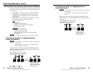
Each local output has a volume control. See "Viewing and
Adjusting the Audio Level” on page 3-8.
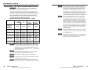
Remote control
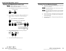
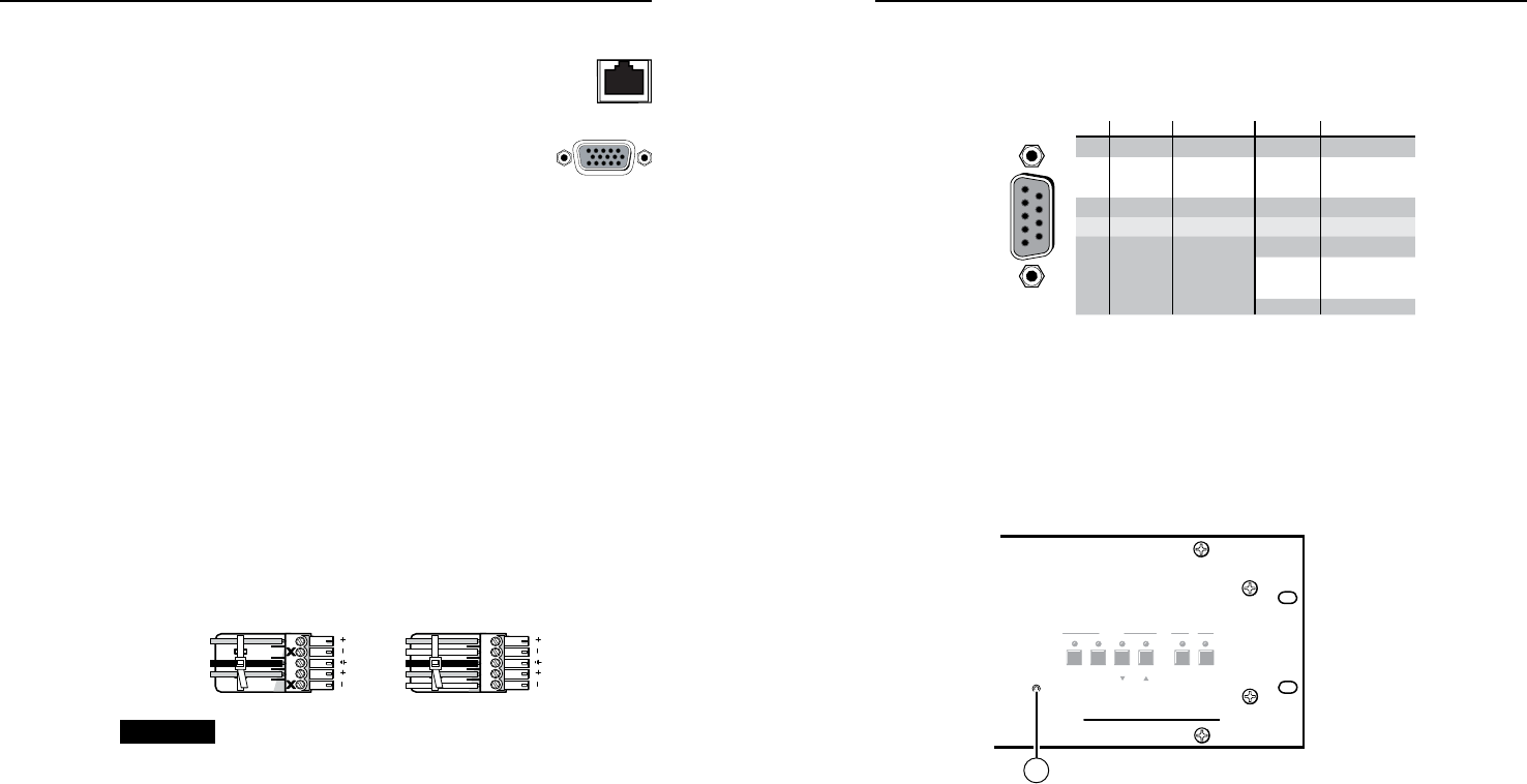
h
Remote port — If desired, connect a control system or computer
to the rear panel Remote RS-232/RS-422 port.
RS-232 Function Pin Function
1
2
3
4
5
6
7
8
9
—
TX
RX
—
Gnd
—
—
—
—
Not used
Transmit
Receive
Not used
Ground
Not used
Not used
Not used
Not used
—
TX–
RX–
—
Gnd
—
RX+
TX+
—
Not used
Transmit (–)
Receive (–)
Not used
Ground
Not used
Receive (+)
Transmit (+)
Not used
RS-422
5
1
9
6
Figure 2-6 — Remote port connector wiring
Power
i
Power connector — Plug the switcher into a grounded AC
source.
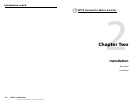
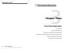
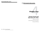
Front Panel
ENTER PRESET VIEW ESC RGBHV AUDIO
CONTROL IO
CONFIG
MTPX SERIES
MTP MATRIX SWITCHER
10
Figure 2-7 — Front panel configuration port
j
Configuration port — If desired, connect a control system
or computer to the front panel Conguration (RS-232) port.
Use an optional 9-pin D to 2.5 mm mini jack TRS RS-232
cable, part #70-335-01.
MTPX • Installation
Installation, cont’d
2-4
MTPX • Installation
2-5