


Extron • System 4
xi
Switcher Series • User’s Manual • P/N 68-412-02 Rev. A
Configuration and ConnectionsHughes Installation
Page 2
"A"
ADP UNV "A"
26-467-01
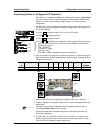
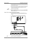
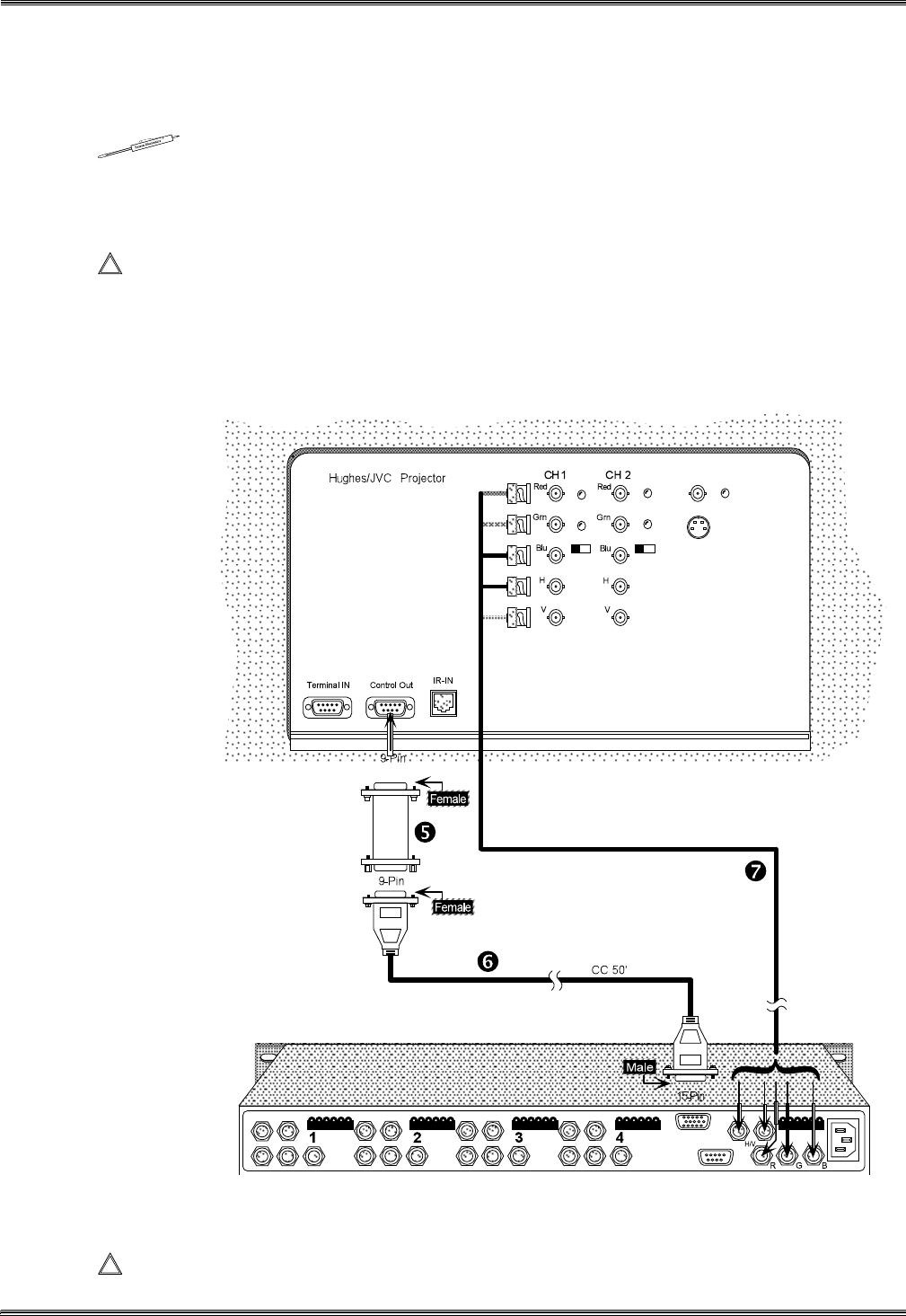
6. Plug the 15-pin HD connector of the Projector Communications Extension cable
(CC 50' or CC 100') into the PJ Comm port on the System 4. The other end has
a 9-pin female connector. Plug this end into the other 9-pin male D connector on
the HU COM adapter.
______ Secure all of the connector screws.
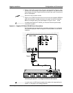
7. Plug the (4 or 5) BNC connectors from one end of the (user-supplied) RGBS/HV
cable onto the System 4 output and those on the other end onto the matching
BNCs on the Hughes panel. See cable diagram in Figure 2-18a or 2-18b.
____________ If installing the Hughes HJT 100/200, you must also follow the special setup
instructions on page 4.
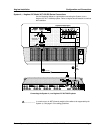
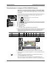
System 4xi - Hughes/JVC Model 300/400 Series Connections
Use illustration below as a guide when connecting the System 4xi to a Hughes/
JVC model 400 projector. Refer to Hughes/JVC documentation to continue the
installation.
Connecting the System 4
xi
to a Hughes/JVC Model 400 Projector
____________ In a rack mount, do NOT allow the weight of the cables to be supported by the
System 4
xi
. See page 2-5 for cabling guidelines.