


Installation
PRELIMINARYPRELIMINARY
c
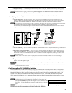
Compositevideoandaudioinputs (”Video”) — Each composite video input (3B and 4B) needs one TP cable. Using TP
cable, connect up to two composite video and audio sources via the PVT CV D input wallplates to 3B and 4B RJ-45 female
connectors.
C
The PoleVault
™
signal transmission method is specific for PVS 204SA Plus switchers working with PVT wallplates.
DO NOT connect to an MTP system. DO NOT connect to an Ethernet/LAN or data transmission system.
N
Do not connect an RGB cable (cable A) to the top ports (3A and 4A) when connecting composite video cables to the lower ports
(3B and 4B).
The PVS 204SA Plus is capable of receiving signals from PVT wallplates located up to 100 feet (30 m) away. The optimum
distance is between 50 and 75 feet (15 and 22 m).
Cable A carries the video signals and cable B carries the audio signal, vertical sync information and 5 VDC current from the PVS
to power the PVT wallplates.
The ports on the rear of the PVS 204SA Plus are color coded for input number and signal type. To ensure correct cable
identification and connection during installation, a sheet of color coded cable labels is supplied. Refer to “Labeling the A/V Inputs”
section in the Polevault System Installation Manual, for details.
When connecting the TP cables to the PVS 204SA Plus, do not cross-connect the cables; connect input 1’s cable A to the RJ-45
port labeled 1A, and input 1’s cable B to the RJ-45 port labeled 1B. Likewise, connect input 2, 3, or 4‘s cable A to its corresponding
numbered A port, and cable B to its B port.
RJ-45 termination must comply with the TIA/EIA T 568A or 568B wiring standards for all connectors. The same standard
MUST be used at both ends of all cables. Refer to the PoleVault System Installation Manual for details.
The cables supplied with the PoleVault system are terminated to the TIA 568A standard.
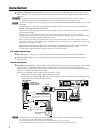
A/V output connections
d
RGBvideooutput — Connect a VGA cable to this female 15-pin HD connector and to the projector for RGB video.
e
Composite(video)output — Connect a cable with an RCA connector to this female RCA jack and to the projector for
composite video.
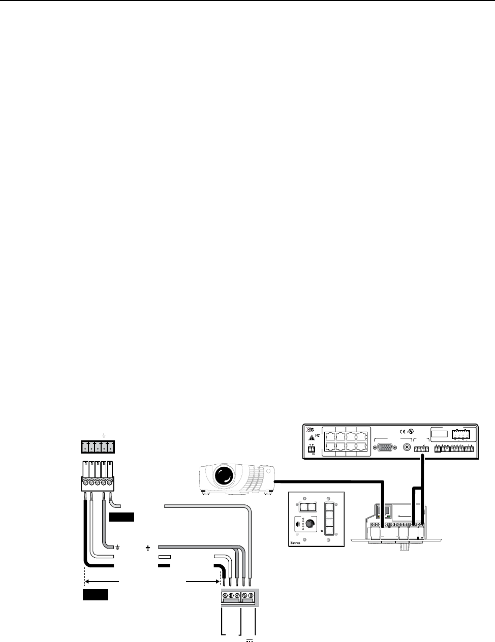
Control connection
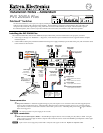
fRS-232/MLC/IRcontrolport — The PVS switcher can be controlled via an RS -232 connection directly from a host computer,
a control system, or a MediaLink Controller (MLC). For IR remote control connect an Extron IR Link to this port.
RS-232 connection can be used to configure the PVS switcher. Connect a cable between this port and the MLC MediaLink
Controller or an optional IR Link IR signal repeater.
The protocol is 9600 baud, 8-bit, 1 stop bit, no parity, and no flow control.
• The MLC provides remote control of input switching and volume.
• The IR Link accepts modulated IR signals from a remote control (e.g., the Extron IR 452 remote) enabling the remote
control to be used for selecting the switcher inputs.
RS-232/MLC/IR
ABC
PVS 204SA Plus
Switcher's Rear Panel
RS-232/MLC/IR Port
NOTE You must connect a ground
wire between the MLC and the
switcher.
MLC 104’s MLS and
Power Ports
NOTE If you use cable that has a drain
wire, tie the drain wire to ground
at both ends.
D
E
Tx RxIR +12 V
MLC 104 IP Plus Front and Side Panels
RS-232
Projector
RS-232
and power
RS-232 12V
MLS PWR
AB
Rx
Tx
GROUND
GROUND
+12V IN
Ground ( )
Tr ansmit (Tx)
B
Receive (Rx)
A
Tr ansmit (Tx)
Receive (Rx)
B
A
PVS 204SA Plus Rear Panel
LR
LR
AUX/MIX IN LINE OUT
AUDIO
PAGING
SENSOR
DO NOT GROUND
OR SHORT
SPEAKER OUTPUTS
1B RGB
1A RGB
2B RGB
2A RGB
3B RGB
/VIDEO
4B RGB
/VIDEO
3A RGB 4A RGB
I
N
P
U
T
S
RS-232 MLC/IR
DC VOL
4/8
Ohms
AMPLIFIED OUTPUT
VOL/MUTE
Tx
ABCDE
Rx IR 12V
10V
POWER
UL 2043 PLENUM RATED
12V
3A MAX
US
LISTED
17TT
AUDIO/VIDEO
APPARATUS
®
RGB
VIDEO
OUTPUTS
CONTROL
N15779
+V
G
SC P
+1 2V OU T
PW R S NS
GR OUN D
GR OUN D
GR OUN D
GR OUN D
GR OUN D
Tx
Rx
HOST/
CONFIG
LAN
PRESS TAB WITH
TWEEKER TO REMOVE
A B
A B E
SCP
COMM
MLS
RS-232
PWR
12V
PROJECTOR
RS-232/IR
Tx /IR
Rx
Tx
Rx
+1 2V IN
+12 VDC input
CONFIG
PROJECTOR
VOLUME
MLC 104 IP PLUS
ON
VIDEO
AUX
VIDEO
PC
IMAGE
MUTE
OFF
1
2
3
4
50 feet (38 m) maximum
N The PVS 204SA Plus power supply can support a typical system: for example, a PVS 204SA Plus, 4 PVT Wallplates,
2 or 4 speakers, and an MLC 104 IP Plus with an IRCM DV+.
• If an SCP 104 is used in the system, the MLC 104 Plus MUST have its own power supply.
• The PVS 204SA Plus provides sufficient power to run an MLC 104 IP Plus or any MLC 52 RS model.
2