


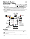
gPagingsensorinput — Connect the optional Priority Page Sensor to this port, to enable audio interrupts during paging
system use.
N
Enable the switcher’s paging sensor port, using Global Configurator or the MediaLink Switchers (MLS) and PoleVault
Switchers (PVS) control software, available at www.extron.com
The Priority Page Sensor Kit (part #70-619-01) is an optional accessory which must be purchased separately.
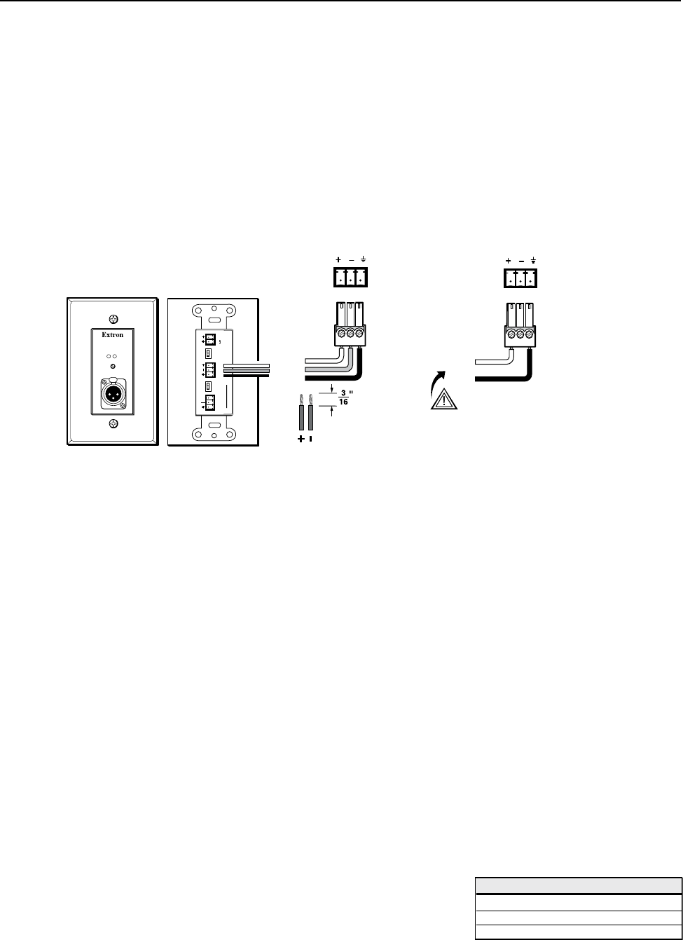
Aux/Mix input connection
hAux/Mixaudioinput — To mix an auxiliary, mono, line-level audio signal (from a wireless microphone receiver, for
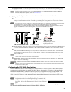
example) with the selected input’s audio, connect the cable from the mono source to this 3-pole captive screw connector.
The signal can be balanced or unbalanced. Wire the supplied blue 3-pole male captive screw connector as shown.
N
Audio input signal is present regardless of the selected input on the switcher. The audio level is not affected by the program volume.
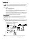
For wired microphones, connect an MP 101 microphone-to-line preamplifier to the Aux/Mix port on the
PVS 204SA Plus, to convert the microphone output to line level. Follow the installation instructions in the user’s manual
supplied with the MP 101 to connect the microphone. See below to wire the MP to the switcher.
Captive Screw
Connector Wire Stripping
(5 mm) MAX.
Balanced
Input
POWER
12V
0.2A MAX
LINE
OUTPUT
REMOTE
10V
VOL/MUTE
ONOFF ONOFF
PHANTOM
LOW CUT
MIC TO LINE
PREAMPLIFIER
MP 101 D
MIC IN
ACTIVE
MUTE
MP 101 D front and rear panels
AUX/MIX IN
To
PVS
Unbalanced
Input
CAUTION
For unbalanced audio, connect the
sleeve(s) to the ground. DO NOT
connect the sleeve(s) to the
negative (-) contact.
NO Ground Here
Tip
Sleeve
AUX/MIX IN
To
PVS
iLineoutaudioport— This port is used for recording or assisted listening devices. It can be configured via RS-232 for fixed
or variable audio output (default is variable). It can be wired for balanced or unbalanced, mono or stereo signal outputs.
jDCVolumecontrolport(Vol/Mute) — This port is used to connect an Extron external volume control module, such as a
VCM, to the PVS 204SA Plus. The range is 0 to 10 V, where 0 V is mute and 10 V is maximum volume. When connected,
the external volume control module is the sole volume controller. Connect the supplied blue, male, 3-pole captive screw
connector to this port.
N
Do not control the PVS volume via RS-232 if this port is connected to a VCM 100, or a VC 50. If a VCM is controlling the
volume, an MLC should not control audio volume via RS-232.
kAmpliedOut — Wire and connect the supplied black 4-pin 5 mm connector to this port, marked “L” and “R” (left and
right) for 4 or 8 ohm speaker output.
C
Do not tie both L and R outputs to each other and/or to ground or it may short the outputs and damage the amplifier.
N
The speaker setup covers two individual speakers of 8 ohm impedance or two pairs of speakers in parallel, where each channel drives
a maximum output load of 4 ohms.
Configuring the PVS 204SA Plus Switcher
The PVS 204SA Plus switcher can be remotely set up and controlled via a host computer or other device (such as a
control system) attached to the rear panel RS-232/MLC/IR port. Alternatively, the switcher can be controlled by
MediaLink Controller (MLC) (connected to the same port) or by an RS-232 device acting through the MLC. The
control device (host) can use either Extron’s Simple Instruction Set (SIS
™
) commands, the Global Configurator
(GC2) program for Windows, or the MediaLink Switchers (MLS) and PoleVault Switchers (PVS) control software, available
at www.extron.com.
RS-232portprotocol: 9600 baud, 8 bit, 1 stop bit, no parity, no flow control.
N
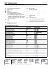
Configuration can also be completed by connecting a 2.5 mm stereo mini
cable (part # 70-335-01, see pinout table at right) to the 2.5 mm port on the
front panel. This port has the same protocol as the RS-232 port on the rear
panel.
N Firmware updates can be made only via the front panel Config port.
Seepage4fortheSISCommand/responseTableforthePVS204SAPlus.
3
9-pin D Connection TRS Plug
Pin 2 PC's RX line Tip
Pin 3 PC's TX line Ring
Pin 5 PC's signal ground Sleeve