


Extron • RGB 202
xi
Series
• User’s ManualPage 3-1
Operation • Controls and Indicators
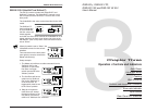
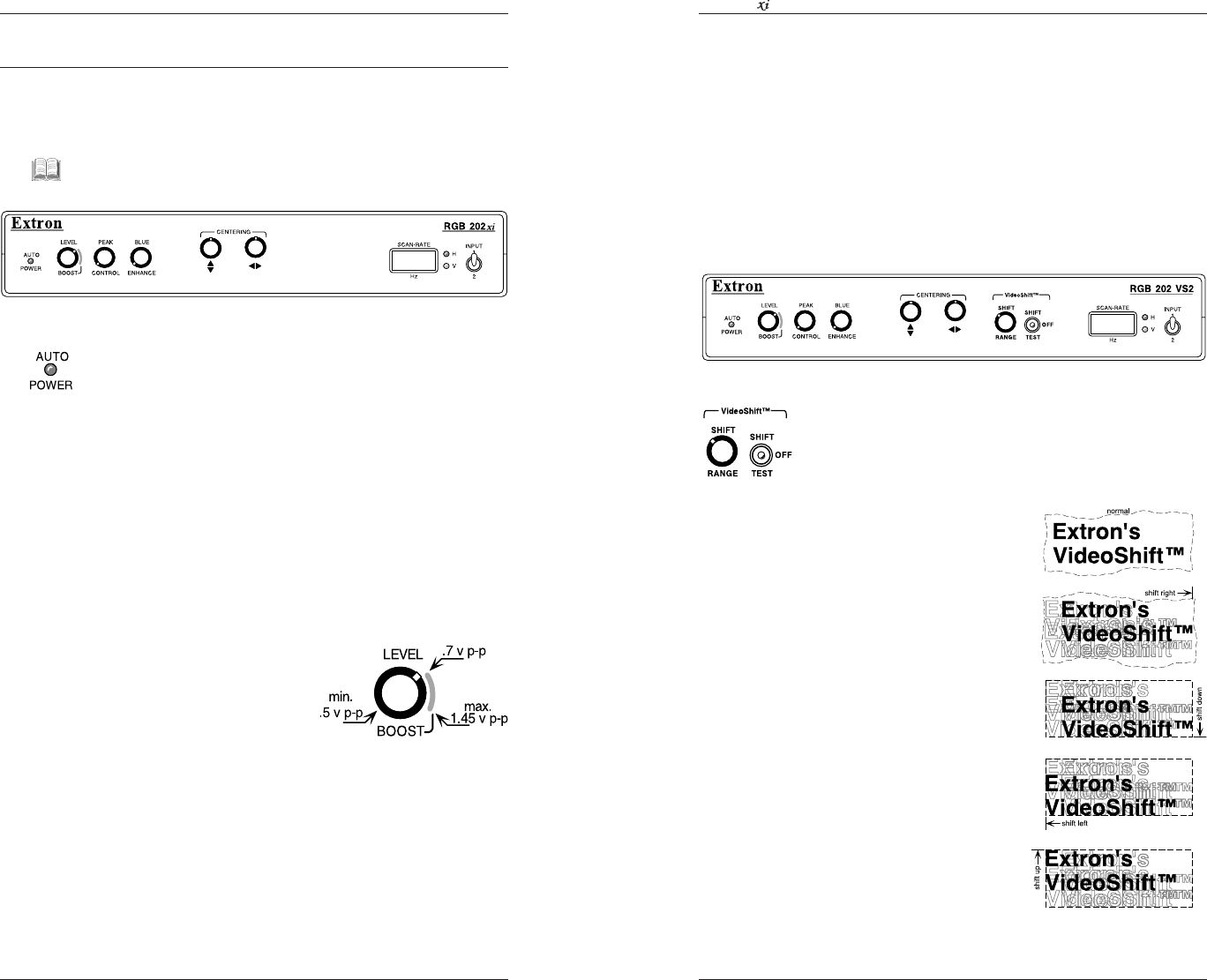
Operating the RGB 202xi
This chapter covers the function of the controls and
indicators on the RGB 202xi, including some examples on
how they are used.
__ If there are any difficulties setting up for the desired
results, see Appendix B for troubleshooting information.
Auto Power Indicator
This LED lights when the RGB 202xi is powered ON.
“Auto Power” means that the computer signal will
automatically turn the RGB 202xi power on.
If the LED does not illuminate, check for computer
operation as well as cable and power connections.
If DIP switch #4 (rear panel) is On, the Auto Power detect
feature is disabled, forcing the power ON as long as it is
plugged to an active power source.
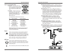
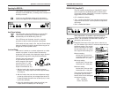
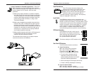
Level and Boost
This control is similar to a contrast adjustment on a data
monitor or projector. It can be used to increase the
brightness and contrast of the displayed image. Observe
the displayed image while using these adjustments.
Following are some examples
of approximate output levels,
with a computer input signal
(such as VGA) of .7 volts
peak to peak (p-p) and the
output is terminated at 75 ý.
1. With the knob in the minimum (counterclockwise)
position, the voltage output level will be approximately
0.5 volts p-p.
2. With the knob to the end of the level adjustment range
(at the top of the red line), the voltage output level will
be approximately the same level as the input (0.7 volts
p-p for this example).
3. At the full clockwise position (past the red line), the
output can be increased up to 1.45 volts p-p.
Extron • RGB 202
xi
Series • User’s Manual Page 4-2
RGB 202 Model Differences
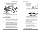
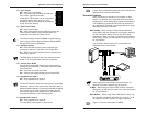
RGB 202 VS2 (VideoShift™)
The VS2 model includes Extron’s VideoShift™ feature.
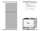
The front panel for the RGB 202 VS2 is shown below.
The section marked “VideoShift™” includes a 3-position
toggle switch to do the following:
• Off – disables the feature.
• Test – enables VideoShift™ at a rate fast enough to see
movement on the screen. Use this position to adjust the
shift range.
• Shift – enables the feature.
When VideoShift™ is enabled, it prevents phosphor
“burn-in” by moving the displayed image around on the
screen. The movement is so slow that it cannot be
detected by the human eye.
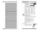
VideoShift movement to the right, down, to the left, up,
etc. The distance of the shift, or movement depends upon
the Range setting. The vertical
shift is in number of lines while
the horizontal shift is in units of
time. Approximate settings are:
Minimum setting:
Vertical shift = 8 scan lines
(4 up and 4 down from center)
Horizontal shift = 0.1 µsec.
Mid-range setting:
Vertical shift = 16 scan lines
Horizontal shift = 0.68 µsec.
Maximum setting:
Vertical shift = 32 scan lines
Horizontal shift = 1.28 µsec.
The actual horizontal distance
will depend upon the video
format. Here are two examples
at maximum range:
SGI – 128 pixels
VGA3 – 64 pixels