


Extron • RGB 202
xi
Series • User’s Manual
Contents
Chapter One • Introduction and Features
Introduction ........................................................................... 1-1
Features .............................................................................. 1-2
Specifications ....................................................................... 1-5
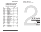
Chapter Two • Rear Panel Connections
BNC Outputs with Auto Sync ................................................ 2-1
Sync Options ........................................................................ 2-1
Remote ................................................................................. 2-3
MBC Power .......................................................................... 2-3
Inputs 1 and 2 ....................................................................... 2-3
Audio Connections ............................................................... 2-4
Termination Switches (DIP 7 and 8) ..................................... 2-4
Laptop, Notebook or Portable Use ....................................... 2-5
Chapter Three • Operation • Controls and Indicators
Operating the RGB 202xi ............................................................. 3-1
Auto Power Indicator ............................................................ 3-1
Level and Boost .................................................................... 3-1
Peak Control ......................................................................... 3-2
Blue Enhance ....................................................................... 3-2
Picture Centering Controls ................................................... 3-3
Scan Rate Indicator .............................................................. 3-4
Input Switch .......................................................................... 3-4
DIP Switch Operation ........................................................... 3-4
Termination Guidelines ......................................................... 3-6
Laptop, Notebook and Portable Applications ........................ 3-7
Chapter Four • RGB 202 Model Differences
RGB 202 VTG ...................................................................... 4-1
RGB 202 VS2 ....................................................................... 4-2
RGB 202 VS SL2 .................................................................. 4-3
Making ShiftLock Cables ...................................................... 4-4
Appendix A • Related Parts and Accessories
Computer-to-Interface Connections .............................................A-1
Monitor Breakout Cables (MBCs) ......................................... A-1
Internal Computer Wiring Kits (ICWKs) ................................ A-1
MBC Buffers .........................................................................A-1
Partial List of MBCs and ICWKs ........................................... A-3
BNC High Resolution Cables ............................................... A-5
Handbook of Computer Interfacing Vol IV ............................A-5
Remote Switch Box ..............................................................A-5
Appendix B • Reference Information
Quick Reference Guide ........................................................B-1
Troubleshooting Tables......................................................... B-3
Removing the Cover ............................................................. B-6
Changing Jumper Settings ...................................................B-7
Page i
Extron • RGB 202
xi
Series
• User’s Manual
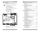
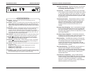
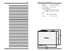
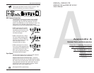
Accessing the Inside
Page B-7
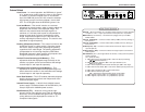
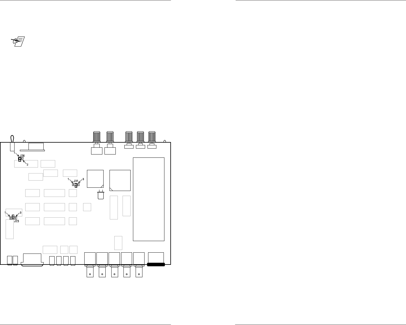
Changing Jumper Settings
There are three jumpers in the RGB 202xi which can be
changed by the user for special applications. They are:
_ Note of the position of the jumper before changing it.
J23 – TTL colors (3-pins)
1 to 2 = 64 TTL Colors (EGA)
2 to 3 = 16 TTL Colors (CGA)
Open (2 only) = Automatic Detect (Default)
The interface normally produces the proper TTL colors.
J26 – Negative Sync (2-pins)
1 to 2 = Sync negative only.
Open = Automatic sync tracking (Default)
J31 – Video Clamp Time (3-pins)
1 to 2 = Backporch (normal)
2 to 3 = Sync Tip (1µ sec from leading edge)
6. When finished, use the previous page as a guide to put
the cover back on.
7. Set the RGB 202xi for normal operation.