


RGB 324/326/340 • Installation and Operation
RGB 324/326/340 • Installation and Operation
Installation and Operation, cont’d
2-14
50/60 Hz
100-240V 0.25A
COM / PWR
Anaheim, CA
ABCDE
COM / PWR
ABCDE
White
Black
Shields
Red
Black
Black
Orange
Brown
Violet
Grey
White
Black
Shields
Red
Black
Black
Orange
Brown
Violet
Grey
21
RLRL
RGB 320
Rear Panel
1
R H/HV
G
B
V
2
R H/HV
G
B
V
RGB 340
Rear Panel
COM/PWRL
AUDIO
R
OUTPUT
RGBHV
ABCDE
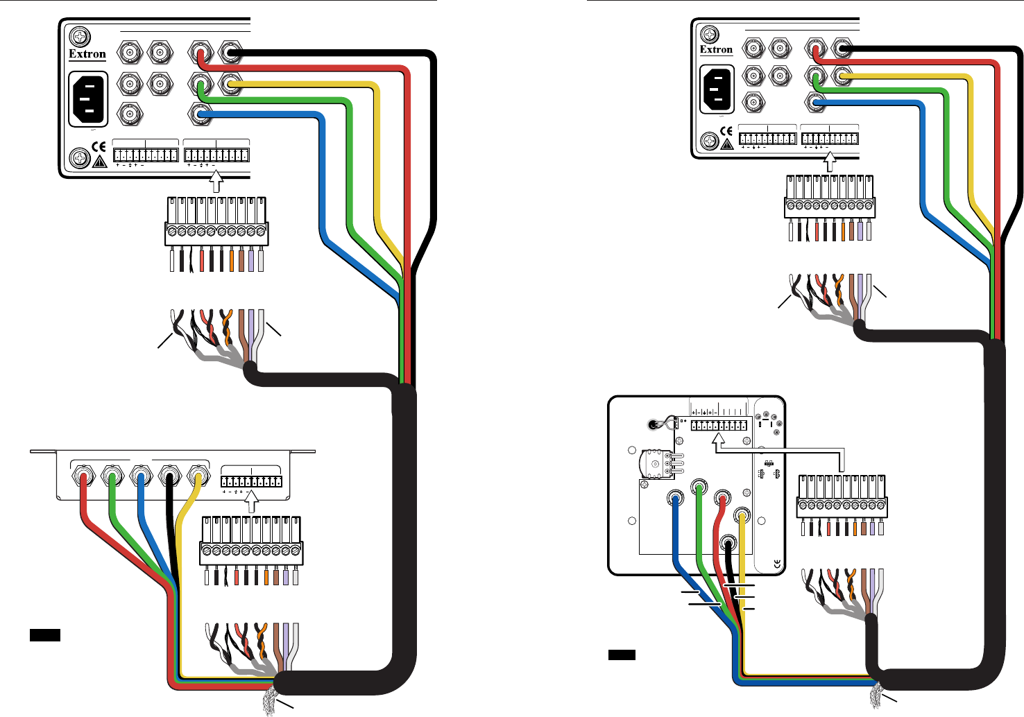
Shielded
Twisted
Pairs
20 AWG
Single
Conductor
Black Mini-Coax (H/HV)
Yellow Mini-Coax (V)
Blue Mini-Coax (B)
Green Mini-Coax (G)
Red Mini-Coax (R)
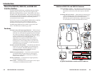
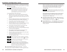
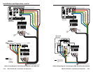
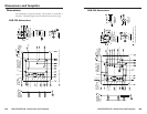
NOTE Cable
connections
must
be
one-to-one
on both ends
of the cable.
Connect the braided shield to ground.
Cable wiring diagram: connecting an RGB 340 to the RGB 320
2-15
50/60 Hz
100-240V 0.25A
COM / PWR
Anaheim, CA
ABCDE
COM / PWR
ABCDE
White
Black
Shields
Red
Black
Black
Orange
Brown
Violet
Grey
White
Black
Shields
Red
Black
Black
Orange
Brown
Violet
Grey
21
RLRL
RGB 320
Rear Panel
1
R H/HV
G
B
V
2
R H/HV
G
B
V
RGB 324/326
J10
J8
J9
J10
J8
J9
.8V.9V
.8V.9V
.7V
.7V
.7V
.8V
.9V
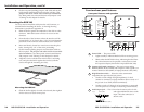
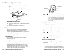
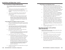
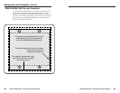
RGB 324, RGB 326
Interface Buffers
Level/Peaking
jumpers
Default =
0.7V (jumper
in the middle
position)
BLUE
RED
GREEN
VSYNC
HSYNC
33-320-01, Rev. C 07 00
BLUE
RED
GREEN
VSYNC
HSYNC
C
O
M
/
P
WR
Audio
33-321-01, Rev. A
A
L
R
BCDE
RGB 324/326
Rear Panel
Shielded
Twisted
Pairs
20 AWG
Single
Conductor
Black Mini-Coax (H/HV)
Yellow Mini-Coax (V)
Blue Mini-Coax (B)
Green Mini-Coax (G)
Red Mini-Coax (R)
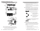
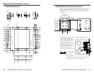
NOTE Cable connections
must
be one-to-one
on both ends of the
cable.
Yellow
Blue
Green
Red
Black
Connect the braided shield to ground.
Cable wiring diagram: connecting an RGB 324/326 to the RGB 320