


RGB 324/326/340 • Installation and Operation
RGB 324/326/340 • Installation and Operation
Installation and Operation, cont’d
2-3
Installation
2-2
1. Cut out the center portion of the cut-out template, which is
provided in appendix B.
2. Place the template (or the wall box) against the installation
surface, and mark the guidelines for the opening on the
wall or furniture.
3. Cut out the material from the marked area with a jigsaw or
small hand saw.
4. Check the opening size by inserting the wall box (if used)
or the interface (if no wall box is used) into the opening.
The box and/or interface should fit easily into the open-
ing. Enlarge or smooth the edges of the opening if needed.
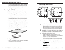
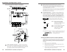
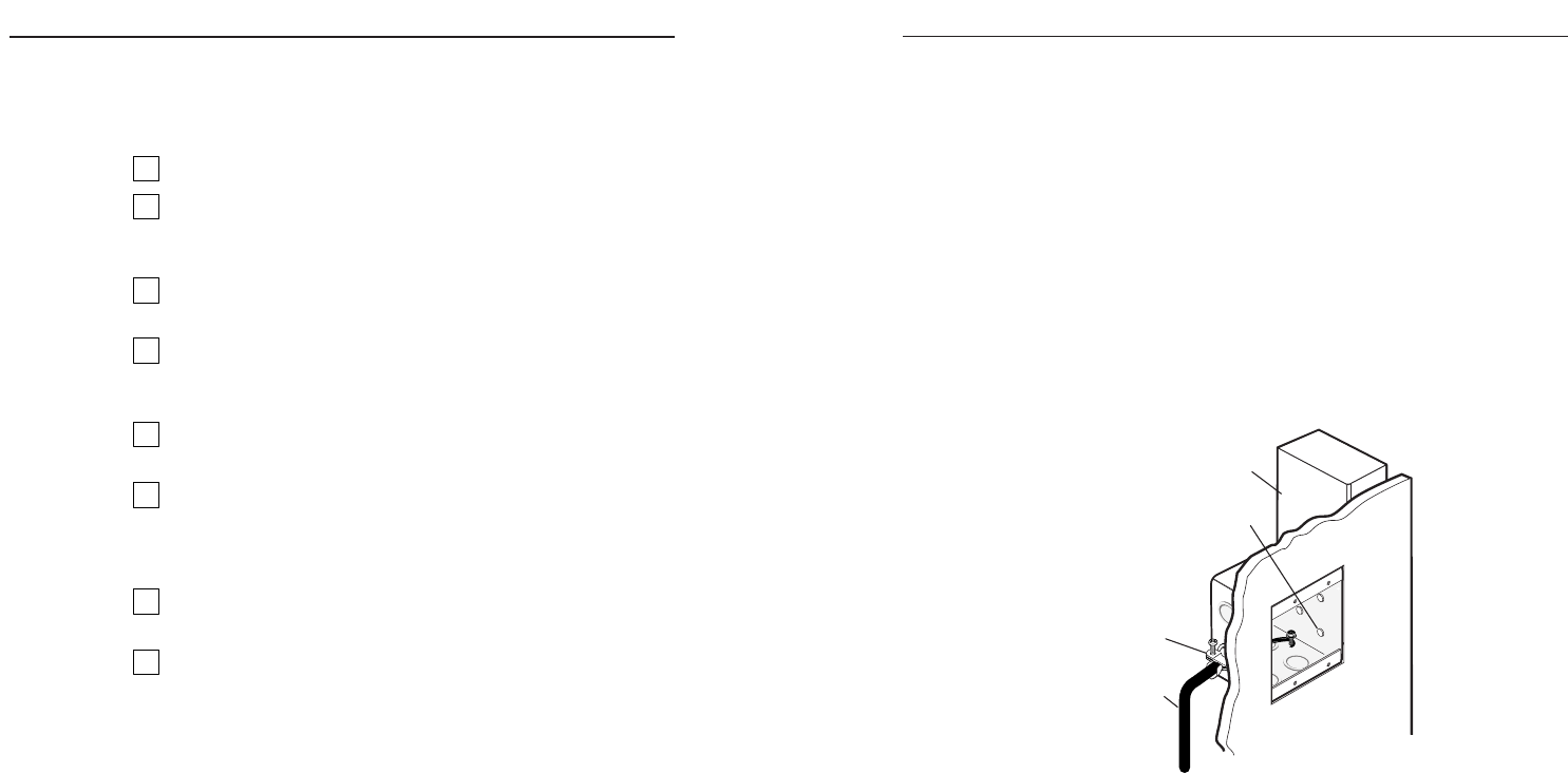
5. Attach the wall box to the wall stud or furniture with nails
or screws, leaving the front edge flush with the outer wall
or furniture surface, as shown in the following illustration.
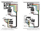
Installation Cable
Cable Clamp
Screws or Nails
Wall Stud
Attaching the wall box to a wall stud
If attaching the wall box to wood, use four #8 or #10
screws or 10-penny nails. A minimum of 1/2 inch
(1.3 cm) of screw threads must penetrate the wood.
If attaching the wall box to metal studs or furniture, use
four #8 or #10 self-tapping sheet metal screws or machine
bolts with matching nuts.
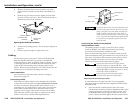
6. Feed cables through the wall box punch-out holes for
connection to the buffer, and secure them with cable
clamps to provide strain relief.
7. Exposed cable shields (braids or foil) are potential sources
of short circuits. Trim back and/or insulate shields with
heat shrink.
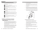
Installation and Operation Instructions
Preparing the site, installing the wall box
(RGB 324, RGB 326)
When selecting an installation site, choose a location that will
allow cable runs without interference, preferably next to a
2” x 4” wall stud or a structural element of the furniture. Allow
enough depth for both the wall box and the cables. You may
need to install the cables into the wall, furniture, or conduits
before installing the buffer.
The RGB 324 and RGB 326 are typically installed in a 2-gang,
3.5-inch deep, metal wall box (provided by Extron). A different
wall box, a plastic box, or no box at all can be used, as long as
the installation conforms to electrical codes and to the
interface’s size requirements. Dimensional drawings and
actual-size cut-out templates are provided in appendix B.
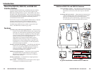
Installation and Operation Overview
To install and set up an RGB 324, RGB 326, or RGB 340 buffer,
follow these steps:
1
Determine the installation location.
2
Prepare the site for installation. Use the template supplied
in the appendix to mark the site, then cut out the
wallboard or wood.
3
Set the jumpers. The jumpers will be inaccessible after
installation.
4
Connect cables to the buffer for power and for audio and
video output. These cables will be inaccessible after
installation.
5
Set the front panel High Z/75 Ohm video termination
toggle switch.
6
Temporarily connect input cables and apply power to the
buffer, the RGB 320, and the input and output devices. See
the “Pre-installation testing/troubleshooting” section in
this manual.
7
Temporarily disconnect power. Remove cables as needed,
and mount the buffer to the wall or furniture.
8
Reconnect cables and power, and adjust centering and
levels as needed.