


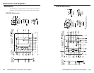
RGB 324/326/340 • Dimensions and Template
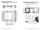
RGB 324/326/340 • Dimensions and Template
Dimensions and Template, cont’d
B-6
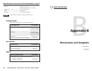
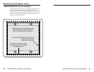
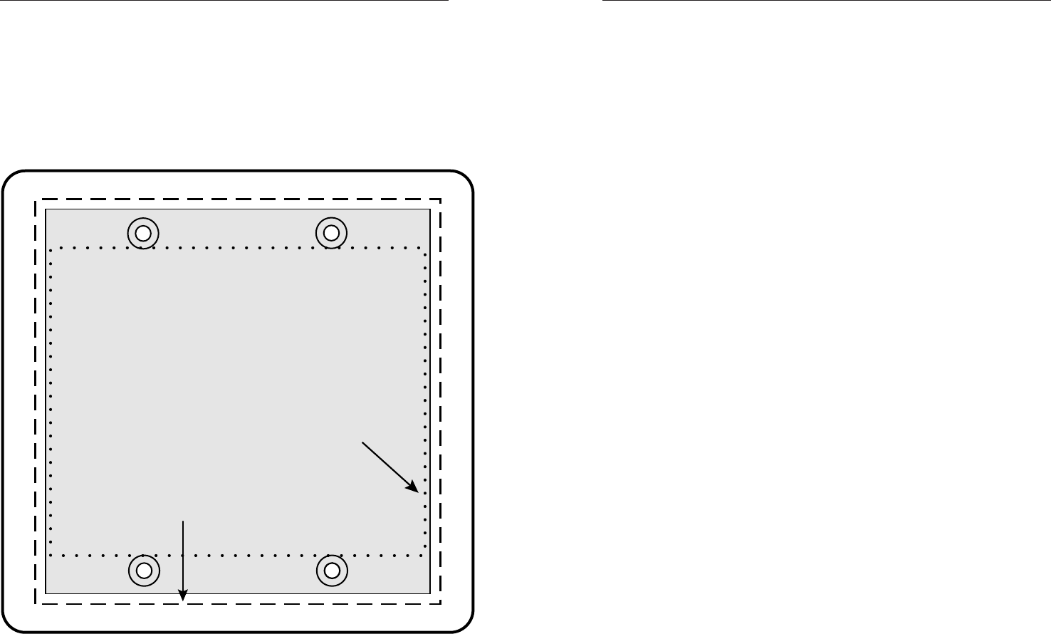
RGB 324/RGB 326 Cut-out Template
Use the full-size template below as a guide to mark and cut the
hole in the wall or furniture through which the buffer will be
installed. The template includes the recommended 0.1” (0.25 cm)
clearance on all sides of the electrical wall box to allow room for
the raised areas surrounding the knockouts. See chapter 2 for
details on installing the buffers.
The light gray area represents the layout of the
electrical box (3.75"H x 3.75"W) against the
rear of the RGB 324/RGB 326 front panel.
The dashed line indicates the cut-out
area (3.95"H x 3.95"W) for installing
the electrical wall box.
To install the interface buffer
without
a wall box,
use the cut-out area (3.00"H)
indicated by the dotted line.
B-7