


Installation and Operation, cont’d
RGB 500 AKM and RGB 560 AKM Installation and Operation2-8
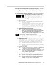
3. If the image appears, but it looks scrambled or cuts in and out, check the
DIP switch settings. If all switches are already set to what should be the
correct settings for the connected input and output devices, try different
settings.
If the display device is digital (including LCD, DLP, and plasma devices),
try changing the vertical sync pulse width (see page 2-4).
Next, try changing the sync options (sync on green, composite sync output),
sync polarity, or serration pulse options, or turn on DDSP (see page 2-3). You
may need to use a combination of settings to achieve a proper display.
4. If the image appears and is stable, but it appears faint or fuzzy, increase the
output gain/peaking by changing the jumpers. If the image is too bright,
decrease the gain/peaking level.
5. If the image appears and is stable, but it has a greenish tint, it may be a result
of using video input with sync on green. Incoming sync on green will not be
stripped from the green signal by the interface.
6. If the image appears and is stable, but it has ghosting or blooming, change
the video input termination. If changing the termination doesn’t solve the
problem, try using a different input cable.
7. For further assistance, call the Extron S
3
support hotline.
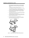
8. After the image is displayed correctly on the screen, you can adjust the
horizontal centering using the front panel knob; however, this adjustment
must be made each time the interface is turned on.
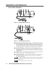
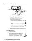
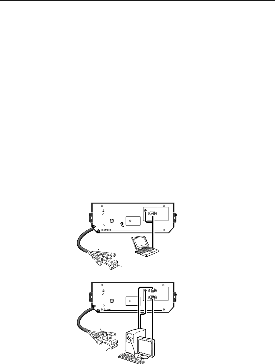
Figure 6 — Typical RGB 500 AKM and RGB 560 AKM applications
RGB 560 AKM with ADSP
TM
RGB 500 AKM with ADSP
TM
BUFFERED
LOCAL OUT
MIN/MAX
H. SHIFT
AUDIO
AUDIO
ID PIN 4
ID PIN 11
INPUT
INPUT
MIN/MAX
H. SHIFT
RGB 500 AKM
Laptop Computer
RGB 560 AKM
SVGA Compatible Computer w/ Audio
6" BNC Female (RGBHV)
To Projection System
Cable
6" BNC Female (RGBHV)
To Projection System
Cable
PC Audio and
Power Cable
PC Audio and
Power Cable
HIGH Z