


SW VGArs / Ars Series Switchers • Installation
SW VGArs / Ars Series Switchers • Installation
Installation, cont’d
2-8
Audio (SW VGA Ars) models only
3
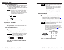
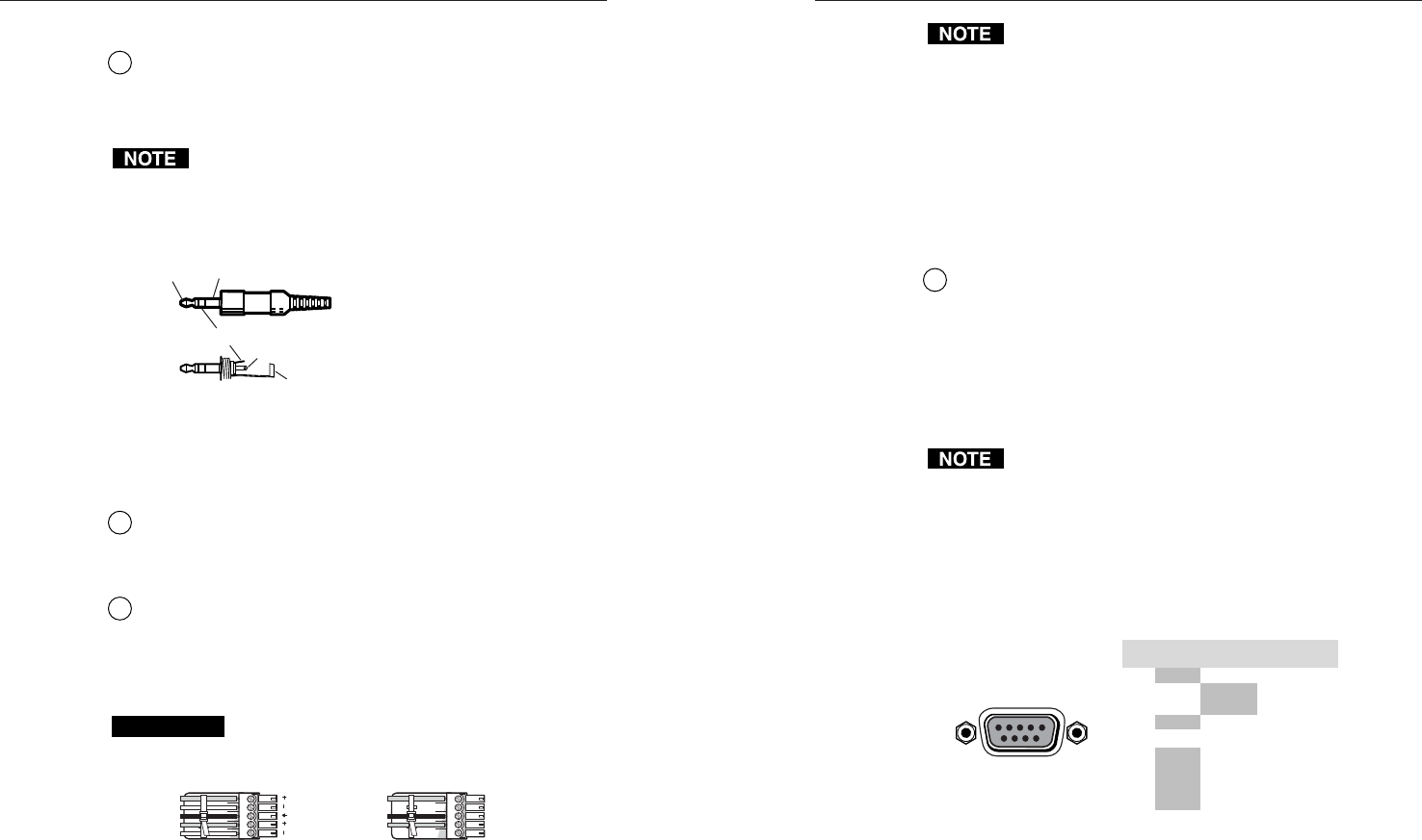
Audio input connector — Plug a 3.5 mm stereo plug into
this jack for unbalanced audio input. Wire the plug as
shown in figure 2-5. The number of inputs available varies
with the switcher model.
When making connections to the switcher using existing
audio cables, see figure 2-5. A stereo audio connector
consists of a tip, ring and sleeve. The ring, tip, and
sleeve wires are also shown on the audio output captive
screw audio connector diagram, figure 2-6.
Tip (L) Sleeve (GND)
Tip (L)
Ring (R)
Sleeve (GND)
Figure 2-5 — 3.5 mm stereo audio plug
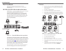
Signal output connection
All models
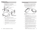
4
Output connector — Connect the monitor to this female,
15-pin HD connector.
Audio (SW VGA Ars) models only
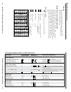
5
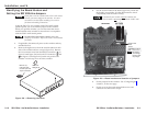
Audio output connector — Insert a 3.5 mm, 5-pole, one-
piece captive screw audio connector into this connector.
Wire the connector as shown in figure 2-6. Use the
supplied tie-wrap to strap the audio cable to the
extended tail of the connector.
CAUTION
For unbalanced audio output, connect the sleeve(s)
to the ground contact. DO NOT connect the
sleeve(s) to the negative (-) contacts).
Unbalanced Stereo Output
Ring
Sleeve (s)
Tip
Tip
Ring
Sleeve (s)
Tip
Tip
Balanced Stereo Output
NO GROUND.
NO GROUND.
Figure 2-6 — Captive screw connector for wiring
audio output
The length of exposed wires is critical. The ideal length
is 3/16” (5 mm).
• If the stripped section of wire is longer than 3/16”,
the exposed wires may touch each other, causing a
short circuit between them.
• If the stripped section of wire is shorter than 3/16”,
wires can be easily pulled out even if tightly fastened
by the captive screws.
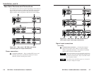
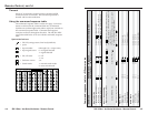
Remote connection
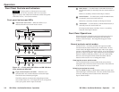
6
Remote RS-232/contact closure connector — Connect a
computer or RS-232 control module to this 9-pin D
connector to allow remote control using the Simple
Instruction Set (SIS
™
) or the Extron graphical control
program for Windows (see chapter 4, “Remote Control”,
for details). You may also connect a KP 6 remote control
keypad (part #60-111-20) or an IR 102 Kit infrared remote
control (part #70-224-01) system to this connector (see figure 2-7).
The switcher can be controlled only by an RS-232 device
OR a contact closure device, not both.
The cable used to connect the Remote port to a computer,
control system, contact closure device, or IR control kit
may need to be modified by removing pins or cutting
wires. If unneeded pins are connected, the switcher may
hang up. See chapter 4, “Remote Control”, for
additional information.
REMOTE
PIN
RS-232
Contact
Closure
Function
1
— In #1 Input #1
Input #2
Input #3
Input #4
Input #5
Input #6
2
TX — Transmit data
3
RX — Receive data
4
— In #2
5
Gnd Gnd Ground
6
— In #3
7
— In #4
8
— In #5
9
— In #6
Figure 2-7 — Remote connector pinout
2-9