


SW VGArs / Ars Series Switchers • Installation
SW VGArs / Ars Series Switchers • Installation
Installation, cont’d
2-10
Identifying the Board Version and
Setting the SW VGA/Ars Jumpers
If you plan to use the switcher with VSW I AAP remote
controls, you must configure the switcher. It is more
convenient to do this before installing it in a rack or
furniture and making connections.
Using the SW VGA/Ars switcher with VSW I AAP control
panels requires you to set internal jumpers in the switcher.
When you open the switcher, you can also check the circuit
board installed in the switcher to ensure that it is compatible
with the VSW I AAP control panels.
On the VSW I AAP remote control, ensure that
jumper J6 is installed. Refer to the VSW I AAP manual
for details.
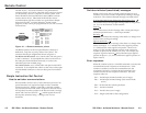
1. If applicable, disconnect all power to the switcher and any
attached devices.
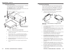
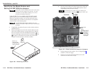
2. Remove the eight screws from the switcher (three on each
side of the switcher and two on top) (figure 2-8). Remove
the two connector nuts from the Remote connector (
6
on
figure 2-3 and figure 2-4) and each VGA connector (
2
and
4
on figure 2-3 and figure 2-4) on the rear panel of the
switcher. Lift the top cover off of the switcher.
SW VGA/Ars SERIES
VGA/AUDIO SWITCHER
6
5
4
3
2
1
MODE
NORMAL
AUTO
A
U
T
O
S
W
IT
C
H
A
C
T
IV
E
Lift Cover
Straight Up
Remove (2)
nuts each side
of each 9-pin and
15-pin connector.
Figure 2-8 — Removing the cover
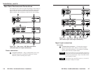
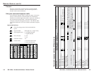
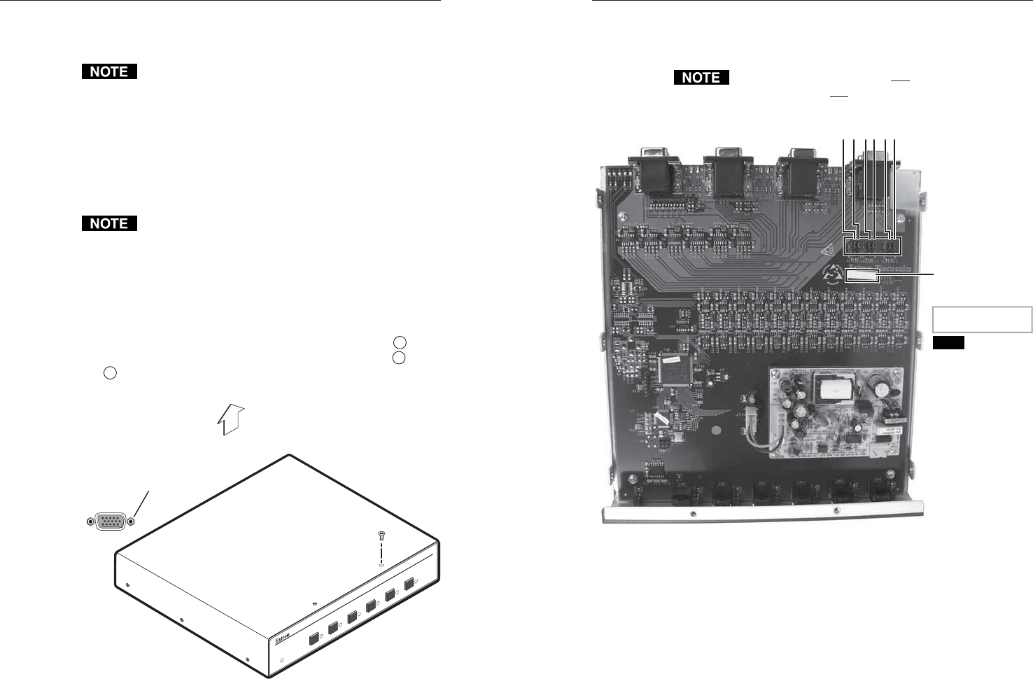
3. See the revision label on the board (figure 2-9), which list
the board’s part number. Use this information to check
compatibility with the VSW I AAP(s).
If the board’s part number is not 20-1118-0n, this
SW VGA/Ars is not compatible with the VSW I AAP.
REAR PANEL
EXTR
ON
20-11
18-02
A
ER:-
nn
nnnnnn nnnn
Revision label
Board:
Version:
ER number
and final digit
of part numbe
r
may change.
JMP5
JMP7
JMP11
JMP15
JMP9
JMP13
EXTRON 20-1118-02 A
ER:- nnnnnnnn nnnn
NOTE
Figure 2-9 — Board version and location of jumpers
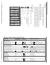
4. Set the jumpers for the switcher. See “Configuring the
switcher”, on the next page.
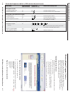
5. Set the cover in place and resinstall the screws and
connector nuts removed in step 2.
2-11