


Audio/Video Switchers • Installation
Audio/Video Switchers • Installation
Installation, cont’d
2-4
Audio models
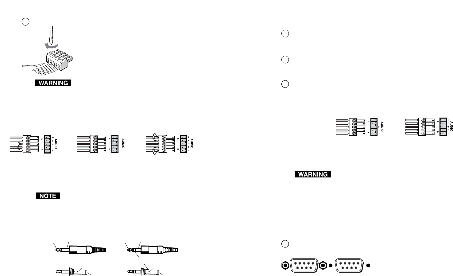
3
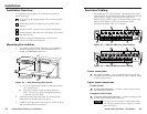
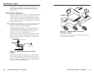
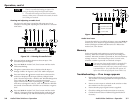
Connections for balanced and unbalanced audio inputs —
Each input has a 3.5 mm, 5-pole captive screw
connector for balanced or unbalanced stereo
audio input. Connectors are included with
each A/V switcher, but you must supply the
audio cable. See figure 2-4 to wire a
connector for the appropriate input type and
impedance level. High impedance is
generally over 800 ohms.
The captive screw connector can easily be
inadvertently plugged partially into one receptacle
and partially into an adjacent receptacle. This
misconnection could damage the audio output
circuits. Exercise care to ensure the captive screw
connector is plugged into the desired input or
output.
Unbalanced Input
Tip
Sleeve
Tip
Sleeve
Balanced Input
Tip
Ring
Sleeve (s)
Tip
Ring
Tip
Ring
Sleeve (s)
Tip
Ring
Balanced Input
(high impedance)
(high impedance) (600 ohms)
600 ohms
600 ohms
Figure 2-4 — Captive screw connector wiring for
inputs
When making connections from the switcher using
existing audio cables, see figure 2-5. A mono audio
connector consists of the tip and sleeve. A stereo audio
connector consists of the tip, ring and sleeve. The ring,
tip, and sleeve wires are also shown on the captive screw
audio connector diagrams, figure 2-4 and figure 2-6.
Tip (left) Sleeve (Gnd)
Tip (left)
Ring (right)
Sleeve (Gnd)
Tip Sleeve
Unbalanced mono Unbalanced stereo
Tip (signal)
Sleeve (Gnd)
Figure 2-5 — Phono audio connectors
The audio level for each input can be individually set, via the
front panel or RS-232, to ensure that the level on the output does
not vary from input to input. See chapter 3, Operation, and
chapter 4, RS-232/Remote Control, for details.
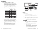
Female
51
96
Male
15
69
2-5
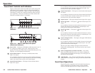
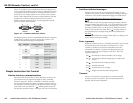
Signal output connections
S-video models
4
S-video output connectors — Connect S-video displays to these
two 4-pin mini DIN connectors.
Composite video models
4
Composite video output connectors — Connect composite
video displays to these two female BNC connectors.
Audio models
5
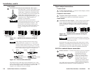
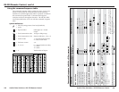
Connections for audio outputs — These 3.5 mm, 5-pole captive
screw connectors output the selected unamplified, line level
audio. Connect audio devices, such as an audio amplifier or
powered speakers. See figure 2-6 to properly wire an output
connector.
Unbalanced Output
Tip
See warning
Sleeve
Tip
See warning
Balanced Output
Tip
Ring
Sleeve (s)
Tip
Ring
Figure 2-6 — Captive screw connector wiring for
audio output
Connect the sleeve to ground (Gnd). Connecting
the sleeve to a negative (-) terminal will damage the
audio output circuits.
By default, the audio output follows the video switch. Audio
breakaway, commanded via the RS-232 link, allows the user to
select from any one of the audio input sources. See chapter 4,
RS-232/Remote Control for details on the RS-232 connection
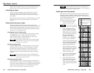
RS-232 or contact closure connection
6
Remote connector — Connect a host device, such as a computer
or touch control panel, an
Extron IR 20 Universal
SYS 4/8/10/AV remote
control, or a remote contact
closure device to the A/V
switcher via this 9-pin D
connector for remote control
using the Simple Instruction
Set™ (SIS), the Extron graphical control program for Windows,
the IR 20 remote control, or a contact closure device.