


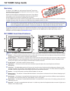
TLP 700MV Setup Guide (Continued)
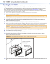
Mounting the TLP 700MV
The TLP 700MV can be mounted in a standard 19 inch equipment rack, using the optional Extron RM 700M rack mounting
kit (part #70-683-01). See the kit for full installation instructions.
For wall-mounting, Extron recommends using the TR 700M trim ring to cover any ragged edges to the hole cut in step 3
below. This optional part can be used with other TouchLink panel accessories (see www.extron.com for details).
To mount the TLP 700MV in the wall, follow these instructions and see the figure below. The steps can be easily adapted if
the unit is mounted in furniture (such as a podium or table).
1. Remove the TLP 700MV from its packaging and determine the best location for installation.
2. Remove the bezel from the TLP 700MV.
CAUTION: Make certain that the correct cutout dimensions are being used before proceeding to the next step.
3. Use the supplied template (part #68-1742-01) to mark the wall or furniture and cut a hole.
4. Ensure all the locking arms are flush with the top and bottom surfaces of the unit. Insert the trim ring and the TLP
700MV to test the hole is the correct size.
5. Remove the trim ring and TLP 700MV. If necessary, use a rasp or a coarse file to enlarge the hole.
6. Run the network cable, two BNC video cables, and power supply cables inside the wall of the hole, leaving enough slack
in the cables to connect them to the back of the TLP 700MV. Use the provided power supply for correct operation.
CAUTION: See the caution in the "Power Supply Connections" section of the TLP 700MV and TLP 700TV User Guide,
available at
www.extron.com, for important information.
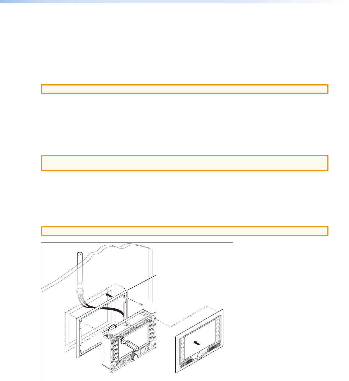
7. Secure the TR 700M trim ring (recommended by Extron) to the wall using four screws (see the figure below).
8. Plug the cables into the rear panel connectors.
9. Push excess cables into the wall cavity and fit the TLP 700MV into the hole.
10. Use a Phillips head screwdriver to tighten the screws. As the screws tighten, the locking arms rotate into position
behind the wall and hold the unit in place.
CAUTION: Do not overtighten the screws because this can damage the unit or the wall.
Bezel snaps to unit
(4 places on each side).
Tighten screws to
rotate locking arms.
Trim Ring (recommended)
secured to the wall
with screws (4).
11. Do not replace the bezel at this time because you will need access to recessed Menu and Reset buttons to configure the
unit.