


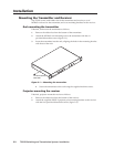
Installation, cont’d
TPS150 Switching and Transmission System • Installation2-6
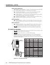
Video output connections
12
RGB/VGA video connector — Connect a VGA cable between this 15-pin HD
female connector and the VGA or RGB input on the display.
13
Composite video connector — Connect a video cable between this BNC
female connector and the composite video input on the display.
14
S-video connector — Connect an S-video cable between this 4-pin mini DIN
female connector and the S-video input on the display.
15
Component video connector — Connect a cable between these BNC female
connectors and the component video input on the display.
Serial connection
16
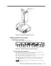
RS-232 connector — Connect a serial cable (figure 2-6) between this 9-pin D
connector and the RS-232 connector on the display for control of the display.
Power connection
17
AC power connector — Plug a standard IEC power cord into this connector
to connect the receiver to a 100 to 240VAC, 50 Hz to 60 Hz power source.
The receiver is protected by a 1.6 A, 250 V, time delay fuse. If necessary,
replace with a time delay fuse with the same amperage and voltage rating.
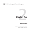
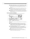
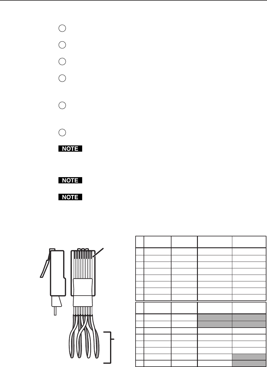
TP Cable Termination
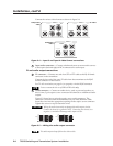
RJ-45 termination must comply with the TIA/EIA T 568A or TIA/EIA T 568B
wiring standards for all connections.
Extron recommends the use of STP or FTP cable only.
Figure 2-8 details the recommended termination of CAT 5 TP cable with RJ-45
connectors in accordance with the TIA/EIA T 568A or TIA/EIA T 568B wiring
standards. You can use either standard, but ensure that you use the same standard
on both ends of the cable.
5
Pin
1
2
3
6
7
8
4
Wire color
White-green
Green
White-orange
White-blue
Orange
White-brown
Brown
Wire color
568 A 568 B
White-orange
Orange
White-green
White-blue
Green
White-brown
Brown
Clip DownSide
1
1&2
3&6 4&5
7&8
2345678
1Pins 2345678
RJ-45
connector
Twisted
Pairs
Blue Blue
5
Pin
1
2
3
6
7
8
4
Wire color
White-green
Green
White-orange
White-blue
Orange
White-brown
Brown
Wire color
568 A 568 B
White-orange
Orange
White-green
White-blue
Green
White-brown
Brown
Blue Blue
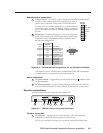
Blue +/V. sync +
Blue –/V. sync –
RS-232 +
Green –/H. sync –
RS-232 –
Red –
Red +
RGB video
signals
Green +/H. sync +
RS-232 +
Y –
RS-232 –
C –
C +
S-video signals
Y +
B-Y +
B-Y –
RS-232 +
Y –
RS-232 –
R-Y –
R-Y +
Component video
signals
Y +
RS-232 +
Video –
RS-232 –
Composite video
signals
Video +
Figure 2-8 — TP cable termination