


2. When the LCD is in the “Display
Programmed Settings” mode, depressing
the Function Button will return the LCD
to normal mode.
The LCD display will also return to “Normal
Mode” automatically after 30 seconds of
button inactivity.
Previous Page/Change Setting Button
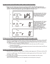
1. When the LCD display is in “Normal Mode”,
repeated pressing of this button will
sequence up through the
input/output/battery parameters and
readings will be displayed.
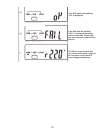
2. When in “Programming Mode”, pressing
this button will change the selected
parameter setting. The new setting will be
displayed on the LCD Measurement display.
On/Alarm Silence Button
1. When utility power is present and the UPS input
circuit breakers are in the “On” position,
depressing and holding this button for 5 seconds
will turn on the UPS.
2. When utility power is not present or the UPS input
circuit breaker is in the “Off” position, depressing
and holding this button for 5 seconds will initiate a
preliminary startup sequence. When “Off” or “BPS”
is displayed on the LCD, depressing the “On”
button again for 6 seconds will start up the UPS in
battery mode (cold start).
3. When the UPS is in utility or battery mode,
depressing this button will silence any audible
alarms.
Off/Bypass Button
1. When the UPS is operating in utility or battery
mode, depressing and holding this button until an
audible beep is sounded will leave the load
powered in bypass mode. To completely shut down
the UPS and connected load, press the Off/Bypass
button until “Off” is displayed on the LCD, and then
turn off the UPS and Bypass input circuit breakers.
The UPS will shut down in about one minute.
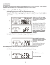
Function Button
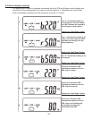
1. When the UPS is operating in utility or battery
mode, depressing the Function Button will switch
the LCD to display the “Programmed Parameter”
settings. When in this mode, depressing the “Next
Page” button will display the next programmed
parameter setting. Repeatedly depress the “Next
Page” button to display all of the programmed
parameter settings.
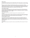
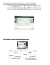
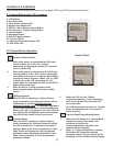
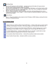
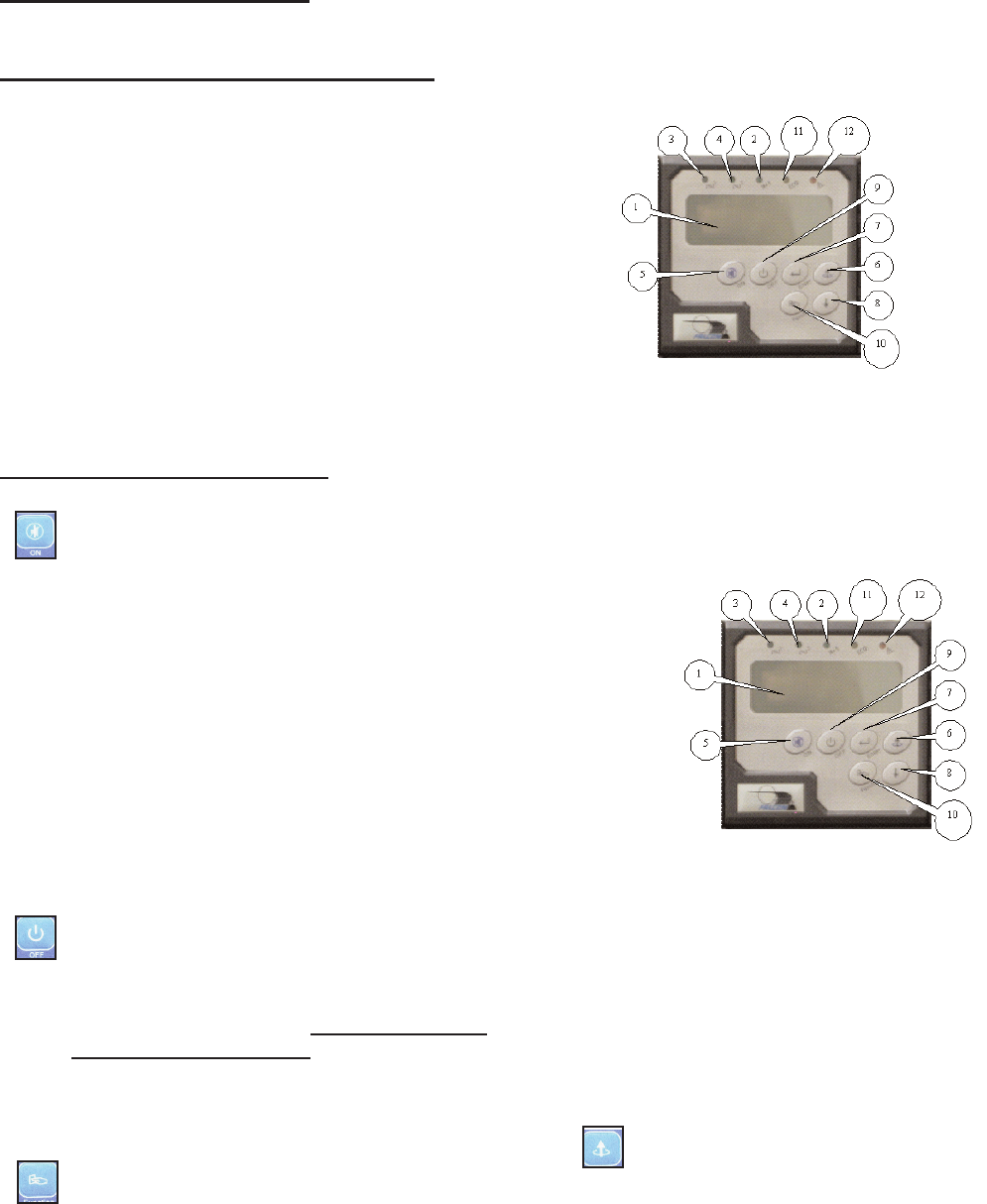
5.0 DISPLAY & CONTROLS
The pictures below outline the various control panel, LED and LCD functions and locations.
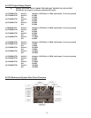
5.2 Control Button Operation
15
5.1 Control Button and LCD Locations
1. LCD Display
2. N+1 Status LED
3. Utility Status Indicator LED
4. Bypass Input Status LED
5. UPS On / Alarm Silence Control Button
6. Previous Page / Change Setting Button
7. Confirm Button
8. Next Page Button
9. UPS Off / Bypass Button
10. Function Button
11. Economy/Green Mode Status LED
12. UPS Alarm LED
Control Panel