


30
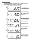
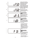
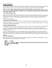
The next parameter displayed
shows the UPS unit address. If
only one UPS is being used, the
address should be set to “d0”
as shown.
If multiple parallel UPS units are
connected on a parallel configu-
ration of 6, 12, 18 or 24kVA, or 6,
12, 18kVA N+1 operation, the
units would be addressed “d0”,
“d1”, “d2” and “d3”. See the
parallel mode configuration sec-
tion of this manual for more
details.
To change between these
settings, depress the “Previous
Page/Change Setting” button.
Repeat pressing the button until
the desired address
setting is displayed. All setting
changes will be saved when
prompted at the end of the
parameter setup.
Depress the “Next Page” button.
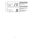
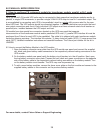
The next parameter displayed
shows the UPS position when
used in a parallel configuration.
The positions are “01”, “02”,
“03”, or “04”.
If only one UPS is being
configured, the position should
be set to “01” as shown.
To change between these
settings, depress the “Previous
Page/Change Setting” button.
Repeat pressing the button until
the desired UPS position
setting is displayed. All setting
changes will be saved when
prompted at the end of the
parameter setup.
Depress the “Next Page” button.
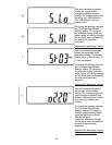
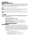
At the end of the parameter
setup mode, you will be prompt-
ed to save the settings.
To save the settings press the
“Confirm” button. If you do not
wish to save the settings, press
the Off / Bypass button for five
seconds. The LCD will display
OFF to indicate the
settings are not saved.
X
IMPORTANT: The UPS must be switched to maintenance bypass mode, shut down and restarted after
entering