12
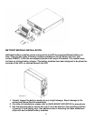
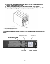
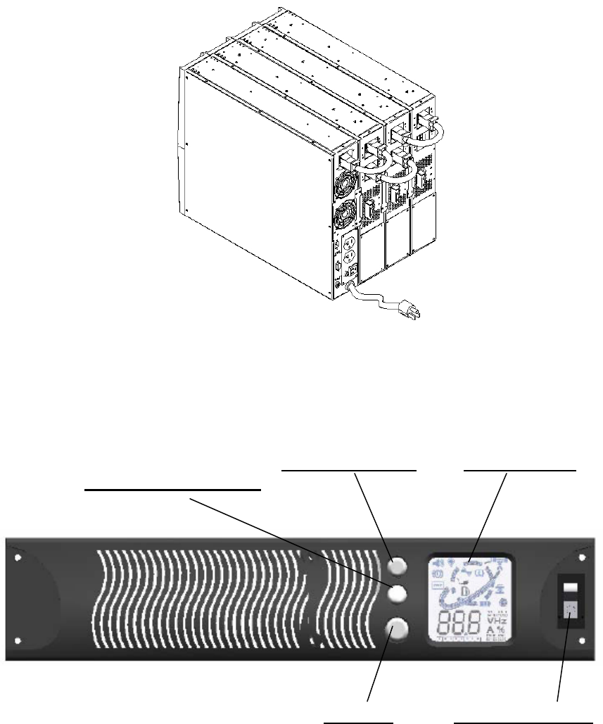
4. Connect the supplied battery modules cable to the rear of the extended battery
module, then to the rear of the UPS.
5. Turn on the battery breaker on the rear of the extended battery module.
6. If an extended battery module has been connected, refer to the Battery Run Time
charts in this manual for the approximate runtime available.
4.0 DISPLAY & CONTROLS
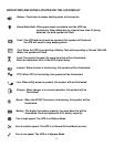
The diagram below shows the basic functions of the front panel for all the XG Series UPS
models.
FUNCTION/TEST LCD DISPLAY
SET/ALARM SILENCE
BYPASS
INPUT BREAKER
XG2.2K-1T


