


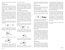

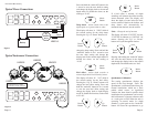

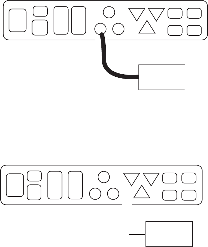
Figure 7
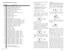
Figure 8
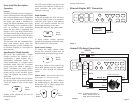
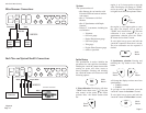
Faria Serial Bus Gateway
Water Pressure Connection
Diagnostic Port Connection
P15
P13
P14
P12 P11
P7
P9
P8P10 P6
P5 P4 P1
P3 P2
P15
P13
P14
P12
P11
P7
P9
P8P10 P6
P5 P4 P1
P3 P2
Water Pressure
Fitting on the
Evinrude Engine
Evinrude
Diagnostic
Computer
To use the Evinrude diagnostic test equipment, you
must remove the “Jumper Plug” from P7 and then
connect the diagnostic unit at P7.
With the diagnostic unit plugged in, the system is
now in the Diagnostic Mode. Normal diagnostic
procedures should be followed.
Note: Instruments are disabled in the Diagnostic
Mode. To return to normal operation, replace the
“Jumper Plug in P7. Turn off power to the
“Gateway.” Reapply power. Serial Bus system is
now in Normal Operation mode.
Page14
Initial Setup
Trim Calibration Page 2
Speedometer selection Page 2
Operation
General Page 3
Speedometer/Depth Sounder
Depth Sounder Page 3
Shallow Alarm Page 3
Deep Alarm Page 4
Keel Offset Page 4
Units Page 4
Speedometer Calibration Page 4
Tachometer/Fuel Management/Hourmeter/ SystemCheck®
Fuel Management Page 5
Instantaneous Fuel Consumption Page 5
Trip Fuel Consumed Page 6
Fuel Remaining Page 7
Fuel Remaining Alarm Setting Page 7
Engine Hourmeter Page 8
SystemCheck® Page 8
SystemCheck Error Codes Page 9
Installation/Harness wiring guide for Evinrude® Engines
Gateway Page 10
Gateway Harness connections
Figure 1 Typical Power Connections Page 11
Figure 2 Typical Instrument Connections Page 11
Figure 3 Evinrude Engine ECU Connection Page 12
Figure 4 Airmar® Tri-ducer Connections Page 12
Figure 5 Miscellaneous Connections Page 13
Figure 6 Fuel Flow and SystemCheck Connections Page 13
Figure 7 Water Pressure Connection Page 14
Figure 8 Diagnostic Port Connection Page 14
Wire Harness/Connections Table Page 15
Table of Contents
Evinrude, SystemCheck, and FICHT are trademarks of Bombardier Motor Corporation