


Page 2
INSTALLATION ON DRAFT HOODS
I
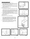
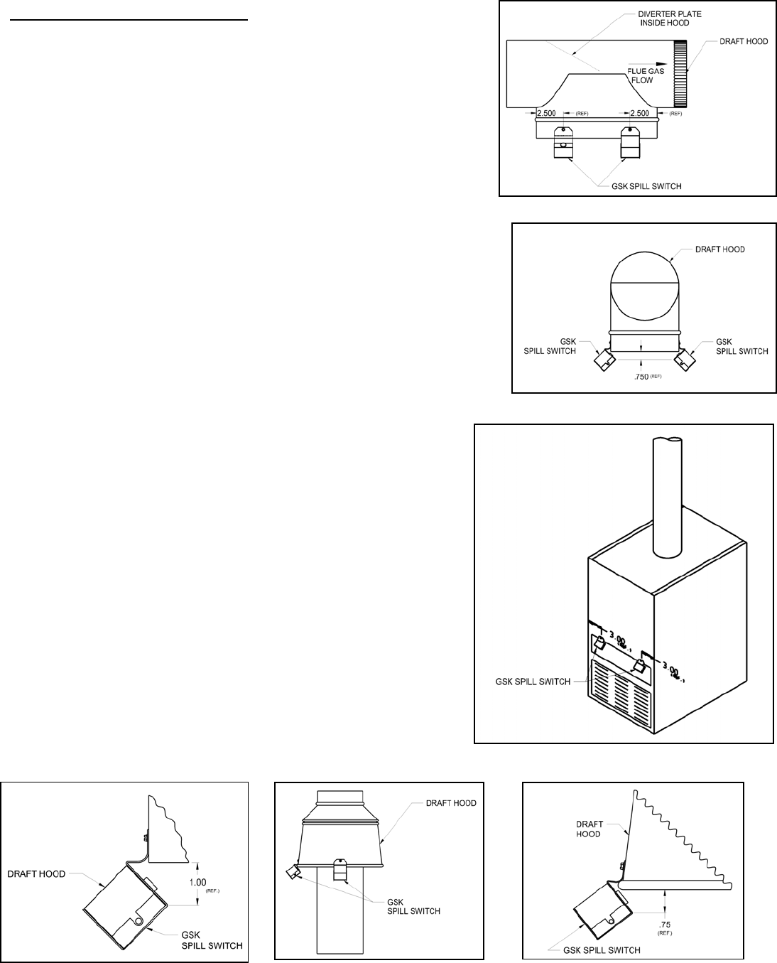
N-LINE HORIZONTAL DRAFT HOOD (See Figures 1 & 2)
1. Two (2) switches are recommended on these hoods. Mount the
switches approximately 2 1/2 inches from the opposite ends and
sides of the draft hood opening. (See Figure 1)
2. The switch should not contact the metal. They should be mounted at
least 3/4 inch below the hood opening. (See Figure 2) Mount with
supplied sheet metal screw.
B
UILT-IN DRAFT HOOD (See Figures 3 & 4)
1. Two (2) switches are recommended on appliances without a factory
supplied spill switch. Mount the switches approximately 3 inches
from the side of the draft hood opening and the second switch (if
used) 3 inches from the opposite side of the draft hood. (See Figure
3) If the appliance has a factory built-in switch, mount a single switch
3 inches from the side opposite the factory switch.
2. The switch should not contact the metal. They should be mounted at
least 1 inch below the hood opening. (See Figure 4) Mount with
supplied sheet metal screw.
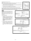
V
ERTICAL DRAFT HOOD
(See Figures 5 & 6 or Figure 13 for water heaters)
1. Two (2) switches are recommended on appliances without a
factory supplied spill switch. Mount the spill switch onto the
bottom edge of the draft hood and the second switch (if used)
approximately 90 degrees from the first switch or 90 degrees
from the factory supplied switch. (See Figure 5)
2. The switch should not contact the metal. They should be
mounted at least 3/4 inch below the hood opening. (See
Figure 6) Mount with supplied sheet metal screw.
Figure 1
Figure 2
Figure 3
Figure 5
Figure 6
Figure 4