


Page 3
DRAFT CONTROLS (See Figures 7 & 8)
NOTE: GSK style switches are designed for draft control models 4" MG1 through 9"
MG1. Larger size draft controls require the FTS Series switches.
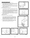
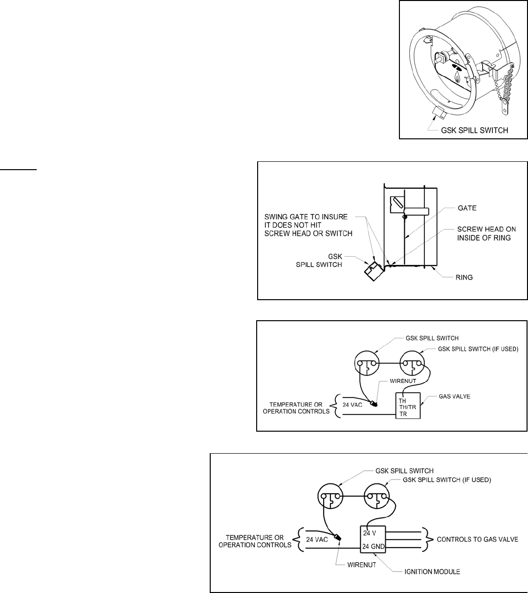
1. Locate the spill switch along the bottom edge of the draft control ring. (See Figure 7)
Mark and drill a 5/32" dia. hole through the ring.
2. Mount the switch with the supplied #5-40 machine screw and nut. Note, the head of
the screw is to be on the inside of the ring. (See Figure 8)
3. Swing the gate to make sure the gate does not hit the screw head or the switch.
NOTE: Mounting the spill switch on the top of the draft control ring will function properly,
but will react slower during a blocked flue condition. If GSK switch(es) are supplied in a
draft control kit, install the switches as directed in the kits instructions.
WIRING
CAUTION: When wiring the spillage switch into
the burner circuit route the wiring and secure
away from any hot surface. Shut off all
electrical power and gas supply to the
appliance before working with any electrical
connections.
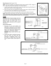
24 V
OLT APPLICATIONS
1. Disconnect the hot lead between the
thermostat or temperature control and the
TH terminal on the gas valve or the TH,TH-
W or 24V terminal on the ignition module.
Check the thermostat anticipator (if
applicable) circuit for proper setting.
CAUTION: Never wire to the 24V GND
terminal.
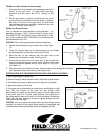
2. Wire the spill switch or switches into series
with this circuit by wiring from the
thermostat or temperature control to the
spill switch or switches then to the gas
valve or ignition module. (See Figure 9 &
10)
Fi
g
ure 8
Figure 9
Figure 10
Fi
g
ure 7