


Page 4
750 MILLIVOLT PILOT GENERATOR APPLICATIONS
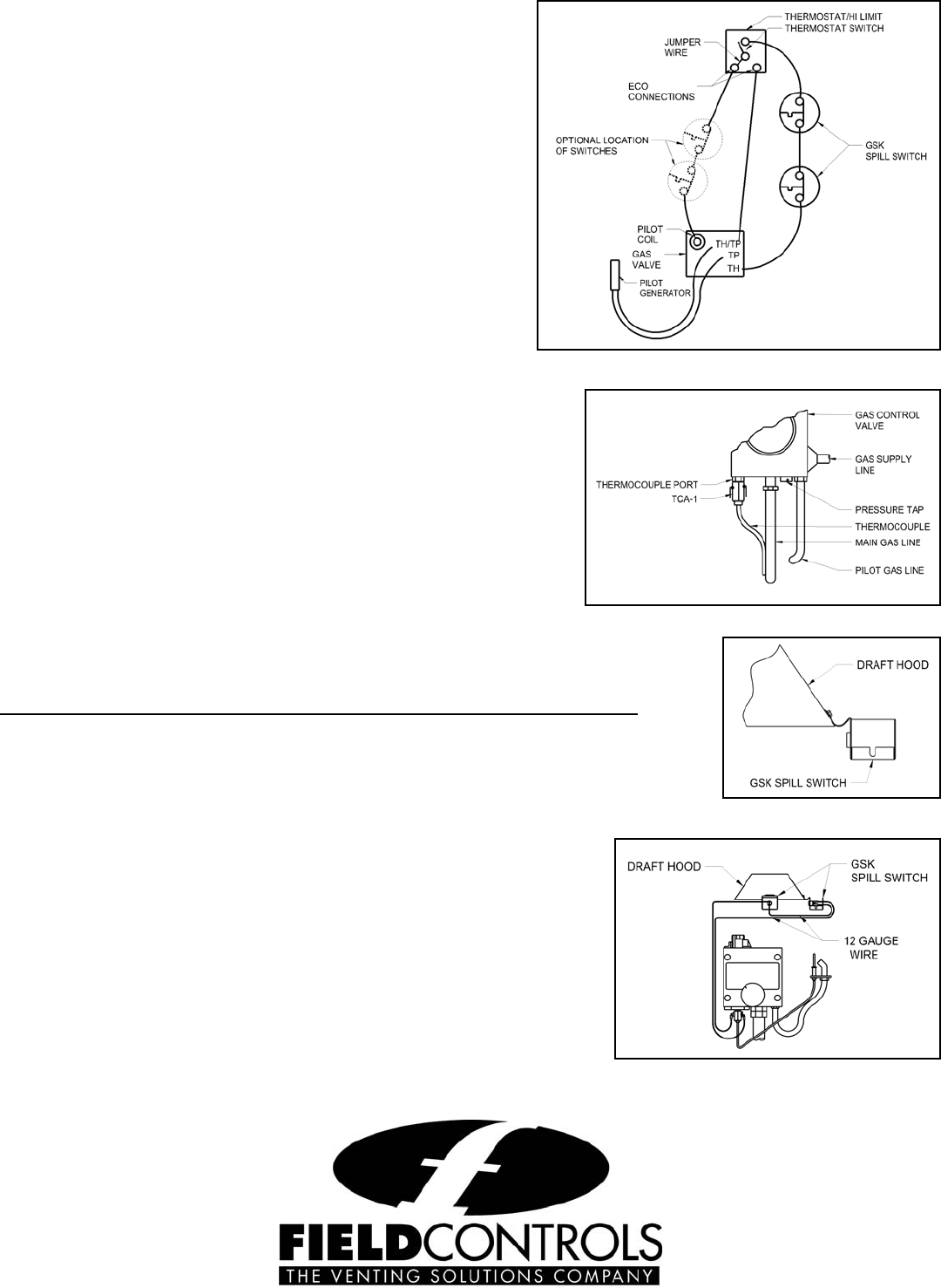
1. Disconnect the hot lead between the thermostat and the TH
terminal on the gas valve. On older bleed tube style
equipment split one lead of the E.C.O. (energy cut off)
circuit.
2. Wire the spill switch or switches into series with this circuit
by wiring from the thermostat to the spill switch or switches
then to the TH terminal on the gas valve. On older bleed
tube style equipment wire switches in series with one wire
of the E.C.O circuit. (See Figure 11)
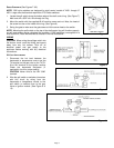
30 M
ILLIVOLT WATER HEATER:
Two (2) switches are recommended for this application. The
application requires a TCA-1 Thermal Couple Junction block
(P/N 46082700 NOT INCLUDED) and a 6 foot length of 12 ga.
two (2) wire conductor (NOT INCLUDED) to wire between the
spill switches and the TCA-1.
CAUTION: Shut off gas supply before working on appliance.
1. Remove thermocouple from gas control valve. (See Figure
12)
2. Thread the junction block into the thermocouple port and thread
the thermocouple into the bottom of the junction block.
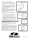
3. Mount the two (2) spill switches onto the draft hood so the
switches do not contact any metal. (See Figure 13)
4. Connect the one terminal of each switch with 12 ga wire and then
connect it to the thermocouple junction block. Next,connect the two
remaining terminals together using a short length of 12 ga wire.
(See Figure 14)
5. Route and secure the wires to the water heater enclosure with acceptable hold down
tabs, keeping the wires away from any hot surface area.
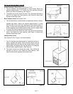
SYSTEM CHECK-OUT PROCEDURE FOR GAS SPILLAGE SWITCH CONTROL
1. Shut off gas supply to appliance(s).
2. Block the flue pipe above the draft control, draft hood or draft diverter.
3. Re-establish gas supply to appliance and re-light pilot (if required).
4. Adjust thermostat to call for heat.
5. Flue gases should be emitting from draft control, draft diverter or draft
hood. Note the location of the most flue gas spillage. Allow
approximately 2 minutes for the system to back up and the gas burner
to shut down. Wait 2 to 3 minutes, reset switches, and re-light pilot. If
the spillage switch does not trip within the 2 minute period, relocate the
switch onto the area where the observed highest spillage occurred.
Then perform this test again.
CAUTION: If for any reason the system has shut down during normal
operation, the cause of the system failure should be investigated and
corrected before resetting the safety switch and relighting the pilot.
P/N 46086300 Rev D 10/08
Figure 12
Figure 13
Figure 14
Figure 11