


Page 2
INSTALLATION OF LS-140A SWITCH ON A POWER VENTED WATER HEATERS WITH PLASTIC PIPE
1. Disconnect Electrical Power to the water heater and shut off the gas
supply to the water heater.
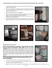
2. Drill a 5/16” diameter hole through the side of the plastic vent pipe at
least 2-inches above the outlet connection on the power venter on the
water heater (See Figure 1).
3. Remove the housing cover of the limit switch.
4. Loosen the two hose clamps and route them through the two mounting
tabs on the ends of the switch housing (See Figure 2).
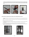
5. Apply bead of high temperature silicone sealant round the base of the
temperature probe (See Figure 3).
6. Insert the temperature probe into the 5/16” diameter hole in the vent pipe
and secure the switch to the pipe with the two hose clamps (See Figure
4).
Wiring the LS-140A Limit switch
Wire the High temperature vent limit switch in accordance with the National
Electrical Code, manufacturer's recommendations and/or applicable local codes.
THE UNIT MUST BE GROUNDED WHEN WIRED TO ANY 120 VOLT
CONTROLS. Check ground circuit to make certain that the unit has been
properly grounded. The wiring should be protected by an over current circuit
device rated at 15 amperes. Caution must be taken to ensure that the wiring
does not come into contact with any heat source. All line voltage and safety
control circuits, between the vent damper and the appliance, MUST be wired in
accordance with the National Electrical Code for Class I wiring or equivalent
methods.
BEFORE STARTING WIRING, TURN OFF ALL ELECTRICAL POWER
TO THE APPLIANCE AT THE APPLIANCE SERVICE SWITCH OR
CIRCUIT BREAKER!!
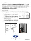
1. Locate the wire connection to the solenoid valve on the gas valve.
2. Cut one of the leads to the solenoid valve and attach a female wire
connector to each wire (See Figure 5 and 6).
3. Attach the two male wire connectors to installer supplied wire leads (See Figure 7), connect them to the
Figure 1
Figure 2
Figure 3
Figure 4
Figure 5