


Page 4
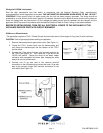
Wiring the LS-550A Limit switch
Wire the High temperature vent limit switch in accordance with the National Electrical Code, manufacturer's
recommendations and/or applicable local codes. THE UNIT MUST BE GROUNDED WHEN WIRED TO ANY 120 VOLT
CONTROLS. Check ground circuit to make certain that the unit has been properly grounded. The wiring should be
protected by an over current circuit device rated at 15 amperes. Caution must be taken to ensure that the wiring does not
come into contact with any heat source. All line voltage and safety control circuits, between the vent damper and the
appliance, MUST be wired in accordance with the National Electrical Code for Class I wiring or equivalent methods.
BEFORE STARTING WIRING, TURN OFF ALL ELECTRICAL POWER TO THE APPLIANCE AT THE
APPLIANCE SERVICE SWITCH OR CIRCUIT BREAKER!!
30 MILLIVOLT WATER HEATER:
The application requires a TCA-1 Thermal Couple Junction block and a 6 foot length of 12 ga. two (2) wire conductor
CAUTION: Shut off gas supply before working on appliance.
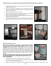
1. Remove thermocouple from gas control valve. (See Figure 11)
2. Thread the TCA-1 junction block into the thermocouple port
and thread the thermocouple into the bottom of the TCA-1
junction block.
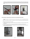
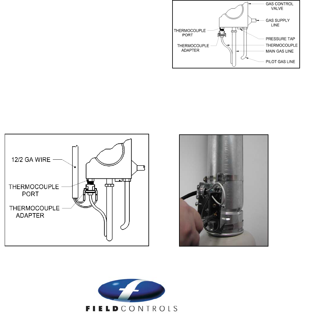
3. Connect the 12 ga wire to the two quick connect terminals on
the TCA-1(See Figure 12). Then route the 12 ga wire to the
LS-550 limit switch. Secure the wires to the water heater
enclosure with acceptable hold down tabs, keeping the wires
away from any hot surface area.
4. Connect one 12 ga wire lead to the common terminal
connection on the limit switch and connect the other 12 ga wire
lead to the normally closed (NC) terminal connection on the
limit switch (See Figure 13).
Figure 11
Figure 12
Figure 13
P/N 46570600 01/09