


Page 3
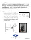
connectors on the solenoid valve and route the wires from the solenoid valve connections to the common terminal
and the normally close (NC) terminal on the LS-140A limit switch (See Figure 8). Also route installers supplied
green grounding wire from the LS-140A limit switch and connect to any convenient grounding surface at the gas
valve.
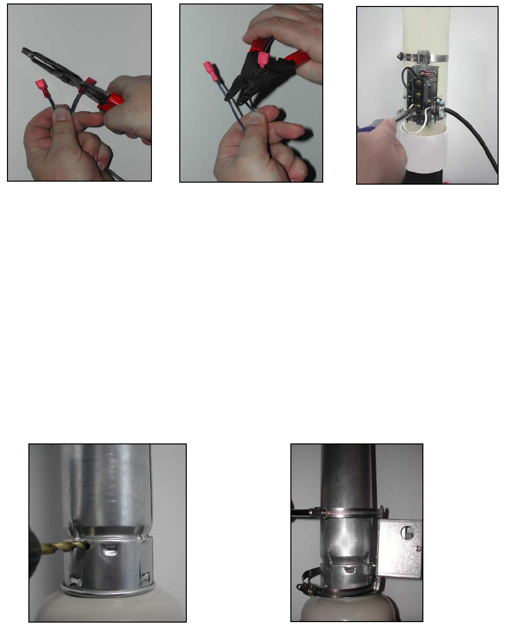
INSTALLATION OF LS-550A SWITCH ON A NATURAL DRAFT WATER HEATER WITH B-VENT
1. Adjust the thermostat on the water heater gas valve to the pilot position and shut off the gas supply to the water
heater.
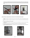
2. Drill a 5/16” diameter hole through the connection joint on the end on the B-vent next the draft hood (See Figure
9).
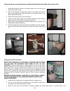
3. Remove the housing cover of the limit switch.
4. Loosen the two hose clamps and route them through the two mounting tabs on the ends of the switch housing
(See Figure 2).
5. Apply bead of high temperature silicone sealant round the base of the temperature probe (See Figure 3).
6. Insert the temperature probe into the 5/16” diameter hole in the vent pipe and secure the switch to the pipe with
the two hose clamps (See Figure 10).
Figure 6
Figure 7
Figure 8
Figure 9
Figure 10