


FortiGuard Analysis and Management Service Version 1.2.0 Administration Guide
50 13-12000-406-20081031
Topology Tool Management
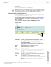
In Edit mode, many different icons (or drawing tools) and shapes help you create
a network diagram. These shapes are available in the Shapes section and are
used to show the different Fortinet products that may be incorporated into your
network. The drawing tools are available below the Topology Tool menus.
To find out about each drawing tool, use your mouse to view each one’s tooltip.
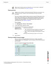
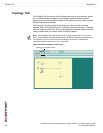
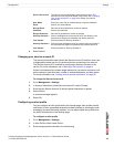
Creating a network diagram
You can create a network diagram easily in the Topology Tool tab using the Edit
mode. In Edit mode, you can choose the shapes you want in your diagram, such
as Fortinet product icons or computers, and connector lines as well as many other
options.
To create a network diagram
1 Go to Management > Topology Tool.
2 Select Edit Mode to access the drawing tools.
3 Draw the diagram using the available drawing tools and shapes.
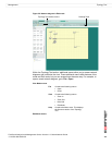
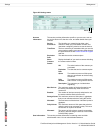
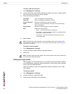
File Contains the following menus:
• New
• Open
• Upload
• Download
• Export
• Save
• Save as
• Close
Edit Contains the following menus:
• Bring to Front
• Send to Back
• Group
• Ungroup
• Delete
View Contains the following menus:
• Zoom In
• Zoom Out
• Hide Grid
• Show Mode
Help Contains the About menu. This displays
the firmware version of the Topology
Tool.
Note: The Edit Mode / View Mode button allows you to switch between the two modes. For
example, if the wording on the button is “Edit Mode”, this indicates that you are using View
Mode and that by selecting the control you will switch to Edit Mode.