


Hardware installation Changing FortiGate-5001A SW11 switch settings
FortiGate-5001A Security System Guide
01-30000-83456-20081023 13
To change or verify the SW11 switch setting
To complete this procedure, you need:
• A FortiGate-5001A board
• A tool for changing the SW11 switch setting (optional)
• An electrostatic discharge (ESD) preventive wrist strap with connection cord
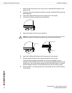
1 Attach the ESD wrist strap to your wrist and to an available ESD socket or wrist
strap terminal.
2 If you have installed the FortiGate-5001A board in a chassis, remove it.
For removal instructions, see “Removing a FortiGate-5001A board” on page 18.
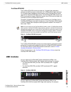
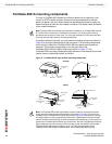
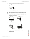
3 Use Figure 8 to locate SW11 on the FortiGate-5001A board.
The top of the FortiGate-5001A board is covered with a copper heat sink. The
printed circuit board is under the copper heat sink. SW11 is located on the printed
circuit board and is accessible from the left side of the FortiGate-5001A board
under the copper heat sink (see Figure 8).
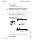
Figure 8: Location of SW11 on the FortiGate-5001A board
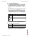
4 If required, change SW11 to the correct setting.
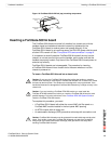
5 Insert the FortiGate-5001A board into a chassis and verify that the board starts up
and operates correctly.
For inserting instructions, see “Inserting a FortiGate-5001A board” on page 15.
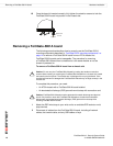
!
Caution: FortiGate-5001A boards must be protected from static discharge and physical
shock. Only handle or work with FortiGate-5001A boards at a static-free workstation.
Always wear a grounded electrostatic discharge (ESD) preventive wrist strap when
handling FortiGate-5001A boards.
FortiGate-5001A
Front Faceplate
Location of SW 11
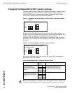
Factory Default (Shelf Manager Required)
ON
SW11
3421
1 Off
2 On
3 Off
4 Off
ON
SW11
3421
1 Off
2 On
3 On
4 Off
Standalone Mode for FortiGate-5020
(no Shelf Manager)
FortiGate-5001A
board (top view)
Note: Figure 8 shows a FortiGate-5001A-DW board. The location of SW-11 is the same on
a FortiGate-5001A-SW board.