


Connecting the FortiGate-5050 chassis to data center DC power and data center ground
FortiGate-5050 Chassis Guide
14 01-30000-87211-20090106
http://docs.fortinet.com/ • Feedback
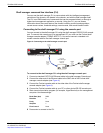
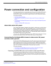
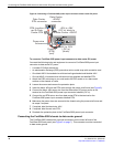
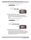
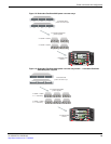
Figure 6: Connecting a FortiGate-5050 power input connector to data center DC power
To connect a FortiGate-5050 power input connector to data center DC power
You need the following tools and equipment to connect a FortiGate-5050 power input
connector to data center DC power:
• A number 2 Phillips screwdriver.
• An electrostatic discharge (ESD) preventive wrist or ankle strap with connection cord.
• One black AWG-14 stranded wire with terminal lugs attached and labelled -48V.
• One red AWG-14 stranded wire with terminal lugs attached and labelled RTN.
1 Attach the ESD wrist strap to your wrist and to an ESD socket or to a bare metal
surface on the chassis or frame.
2 Loosen the screws and remove the protection plate.
3 Insert the black -48V and red RTN wires through the power wire fixture (see Figure 6).
4 Connect the black -48V power wire from the data center DC power source to the
terminal on the FortiGate-5050 power input connector labelled (-DC in).
5 Connect the red RTN return wire from data center RTN to the terminal on the
FortiGate-5050 power input connector labelled RTN.
6 Make sure the power wires are secured to the chassis using the power wire fixture and
tie wraps if required.
7 If required, label the black wire -48V.
8 If required, label the red wire RTN.
9 Re-attach the protection plate to the FortiGate-5050 power input connector.
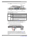
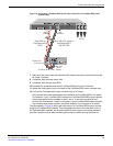
Connecting the FortiGate-5050 chassis to data center ground
The FortiGate-5050 chassis has a ground connections on the lower left side of the
FortiGate-5050 back panel (see Figure 2 on page 7). This connector must be connected
to data center ground.
-48V to -58V
(-DC in)
(black)
Positive
(RTN)
(red)
-48V to -58V
(-DC in) black to
Data Center -48VDC
Data Center
-48VDC
connector
RTN (positive)
red to Data
Center RTN
Data Center
RTN connector
Power wire
fixture