


Turning on FortiGate-5050 chassis power
FortiGate-5050 Chassis Guide
22 01-30000-87211-20090106
http://docs.fortinet.com/ • Feedback
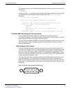
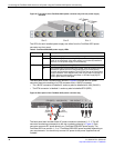
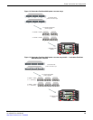
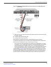
Figure 15: Wiring the FortiGate-5053 power converter tray
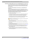
To connect the FortiGate-5050 chassis to data center ground
The FortiGate-5053 power converter tray does not have a ground connector. So, even if
you are using a FortiGate-5053 power converter tray to supply DC power to your
FortiGate-5050, you must use the procedure “To connect the FortiGate-5050 chassis to
data center ground” on page 15 to connect the FortiGate-5050 to data center ground.
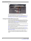
Turning on FortiGate-5050 chassis power
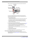
If you are using a FortiGate-5053 power converter, connect the FortiGate-5053 power
converter to AC power. When the FortiGate-5020/5050 power supplies start up the power
supply fans should begin operating. Each FortiGate-5020/5050 power supply has two
front panel power LEDs (see Figure 8 on page 16). When the FortiGate-5053 power
converter is operating normally, both of the FortiGate-5020/5050 power supply LEDs
should be lit for each connected power supply.
If you are using data center DC power, turn own the power to the chassis according to the
requirements of your data center DC power system.
Once the FortiGate-5050 chassis is connected to DC power you can turn on power to the
chassis by switching on the circuit breakers at the back of the chassis (see Figure 2 on
page 7 for location of the circuit breakers).
The FortiGate-5050 chassis powers up. If the FortiGate-5050 is operating correctly, the
Power LED on the right side of the chassis front panel should be lit (see Figure 1 on
page 6). As well, the Status LED on the FortiGate-5050 shelf manager front panels should
be lit (see Figure 3 on page 8).
When the chassis first starts up you should also hear the cooling fans operating.
In addition, if any FortiGate-5000 series boards have been installed in the chassis they
should power on and their front panel LEDs should indicate that they are operating
normally.