


Operational Description
Header and Jumpers Blocks
Using the ASB520 MC68HC908QT2 Based Infrared Remote Control Reference PC Board DRM045
MOTOROLA Operational Description 13
2.4 Header and Jumpers Blocks
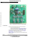
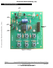
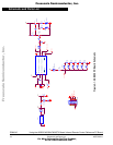
There is one 16-pin header (2 x 8-pin), J1, and four 2-pin jumper blocks,
JP1–JP4, on the PC board. See Figure 2-1 for their locations on the PC board.
The header and jumper functions are described as follows.
J1: Jumper block J1 is used to program the MC68HC908QT2, located in
the center of the PC board. The connections to this board follow the
standard MON08 connector scheme. It is also used to put the ASB520
system into test mode. In a production environment, J1 could be
replaced by a “bed of nails” test fixture to reduce PC board parts costs.
JP1: Jumper block JP1 is on the PC board measure the current consumed
by the microcontroller. Its primary purpose is to measure stop current of
the microcontroller. A small trace on the bottom of the PC board must
be cut to use this feature. When using this feature to measure stop
current you should remove shorting jumper JP2. Removing the shunt
from JP2 removes the system’s 470 µF bulk capacitor. Removing that
capacitor will improve accuracy of the current measurement, as large
capacitors have leakage current associated with them. Select the
lowest voltage rating bulk capacitor for your circuit as possible because
lower voltage rated ones tend to have less leakage than higher voltage
ones for a given capacitance value.
JP2: Jumper block JP2 disconnects the bulk capacitor during FLASH
programming and optionally during stop current monitoring. The value
of the capacitor is large enough to cause power switching issues when
using the Cyclone programmer. During the programming procedure,
the Cyclone programmer cycles power to the target PC board. Large
value bulk capacitors greater than approximately 100 µF present
excessive currents to the Cyclone programmer and interfere with the
POR circuit of the target’s microcontroller as voltage on larger
capacitance devices do not discharge fast enough during voltage
cycling.
The purpose for the bulk capacitor is two fold: First is tends to help lower
the effects of the battery’s internal resistance during periods of high
current demands while the IR LED is being modulated. This is a
particular benefit toward the battery’s end of life period, when its internal
resistance is increasing. Second, if a system uses RAM to store user
information, the bulk capacitor will retain voltage to the microcontroller
during battery changes.
JP3: Jumper block JP3 disconnects pullup resistor, R9, during FLASH
programming.
JP4: Jumper block JP4 disconnects LED drive circuitry during FLASH
programming.
Frees
cale Semiconductor,
I
Freescale Semiconductor, Inc.
For More Information On This Product,
Go to: www.freescale.com
nc...