


Using the ASB520 MC68HC908QT2 Based Infrared Remote Control Reference PC Board DRM045
MOTOROLA Pin Description 15
Designer Reference Manual — DRM045
Section 3. Pin Description
3.1 Introduction
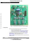
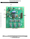
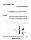
There is one connector resident on the control board, labeled J1. It is the
MON08 connector. The following subsection describes signals on connector
J1.
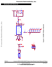
3.2 16-Pin Connector J1
Signals to and from the MON08 connector are grouped together on 16-pin
(2 x 8-pin) ribbon cable connector J1. Pin assignments for connector J1 are
shown in Table 3-1. In a production environment, J1 could be replaced by a
“bed of nails” test fixture to reduce PC board parts costs.
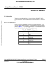
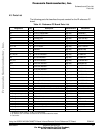
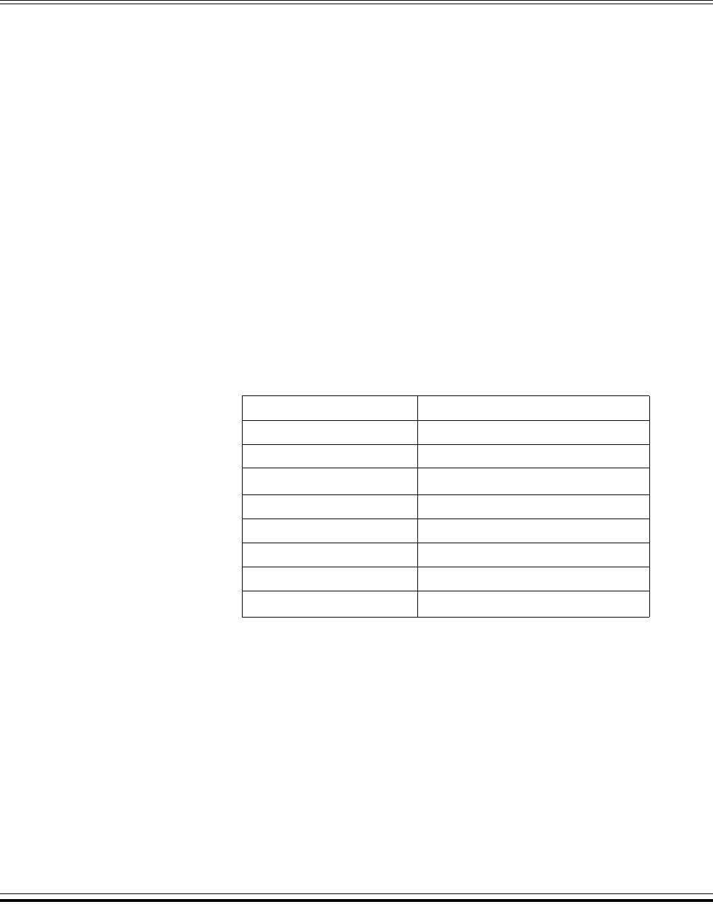
Table 3-1. MON08 Pin Assignments
Pin Number Function
1, 3, 4, 5, 7, 9, 11,14, 16 No connect
2GND
6
V
TST
(PTA2)
8COM (PTA0)
10 MOD1 (PTA4)
12 MOD0 (PTA1)
13 OSC1 (PTA5)
15
V
DD
Frees
cale Semiconductor,
I
Freescale Semiconductor, Inc.
For More Information On This Product,
Go to: www.freescale.com
nc...