


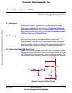
Design Considerations
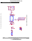
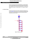
Switch Circuitry
Using the ASB520 MC68HC908QT2 Based Infrared Remote Control Reference PC Board DRM045
MOTOROLA Design Considerations 23
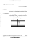
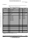
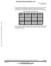
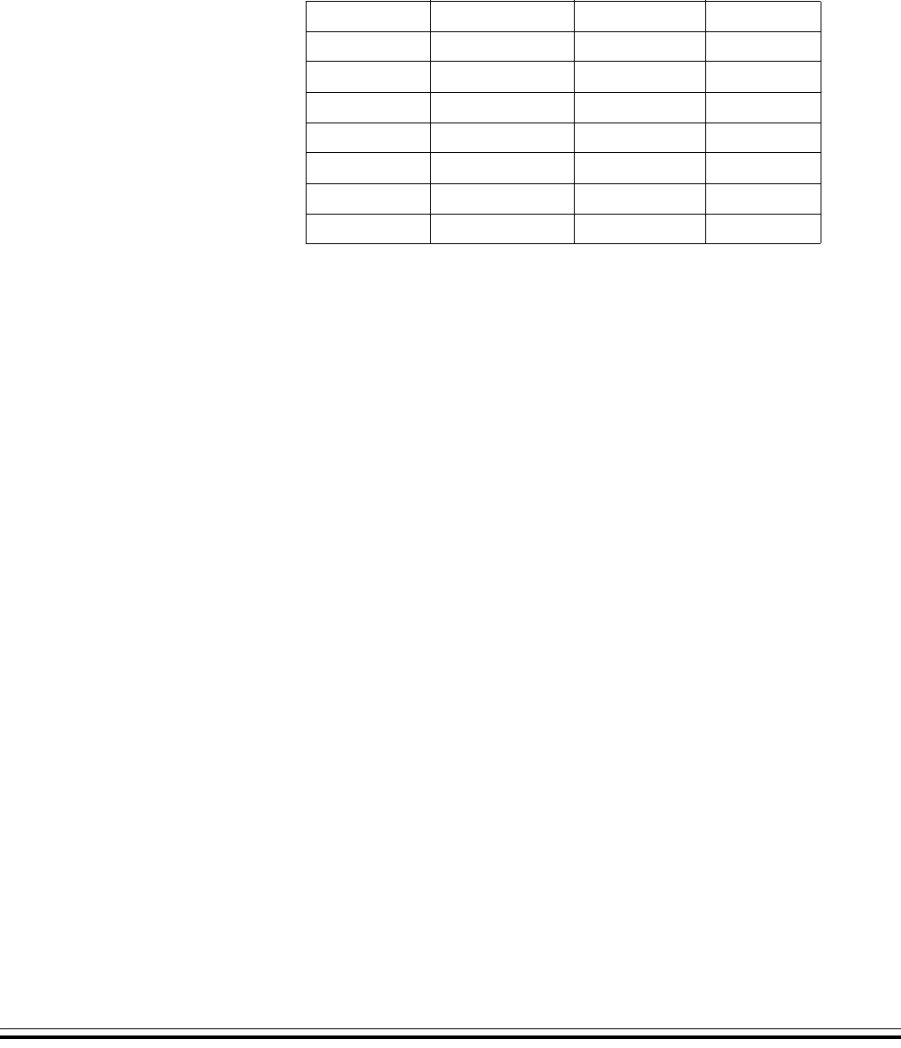
The spreadsheet in Table 5-1 gives the decimal values seen by the A/D, based
on which switch is depressed. Because the voltage from the switches is
ratiometric to V
DD
, power supply variation will have no effect on A/D readings.
The ±6% values in Table 5-1 indicate worst case values, as the resistors used
in the design are ±5%. The software uses the minimum values from the table
to decode the switches.
Table 5-1. Switch Input A/D Values
Switch Ideal Value Minus 6% Plus 6%
No switch 255 239.7 255
Power 170.5 160.3 180.7
Play 127.7 120 153.3
Forward 79.9 75.1 84.7
Reverse 40.8 38.4 43.3
Pause 14.8 13.9 15.6
Stop 0 0 0
Frees
cale Semiconductor,
I
Freescale Semiconductor, Inc.
For More Information On This Product,
Go to: www.freescale.com
nc...