


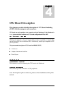
These jumpers allow to use Mainboard’s I
2
C connector/EEPROM memory even in the
case, when CPU itself doesn’t provide the I
2
C interface. When both of these jumpers are
SHORT, the CPU’s HRQ signal is connected to the Mainboard’s SDA signal (via J19) and
#HAK signal is connected to SCL signal. An user can then program the #HAK, HRQ
signals to behave as I
2
C interface.
When short, these jumpers connect the 32.768 kHz crystal to the Bus Interface connector
X1A, X0A pins.
When short, these jumpers connect the 4MHz crystal to the Bus Interface connector X0,
X1 pins.
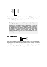
This button can be used for reseting the CPU.
While this button is pressed, the CPU stays in the standby mode (all oscillators are
stopped, all I/O pins are set to high impedance state, special purpose registers such as the
accumulator are reset to their default values, but content of internal RAM is preserved)
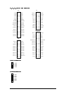
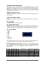
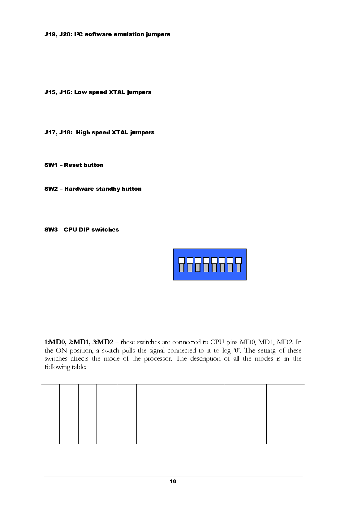
1: MD0
2: MD1
3: MD2
4: S-R
5: S-H
6: H-R
7: AD00 (P00)
8: AD01 (P01)
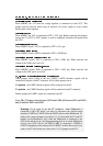
These switches should be used only when using the CPU board without Mainboard, or
with the FPGA disabled (see the description of J29 in the Mainboard section).
MD2 MD1 MD0 AD00/
P00
AD01
/P01
Mode name Reset vector area External data
bus witdth
ON ON ON OFF OFF External vector mode 0 External 8
ON ON OFF OFF OFF External vector mode 1 External 16
ON OFF ON OFF OFF External vector mode 2 External 16
ON OFF OFF OFF OFF Internal vector mode Internal (Mode data)
OFF ON ON X X Reserved
OFF ON OFF X X Reserved
OFF OFF ON ON ON Async serial programming
OFF OFF OFF X X Reserved
8 7 6 5 4 3 2 1
ON