


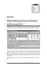
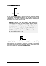
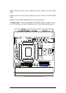
4: S-R – if ON, this switch connects the RES pin of the K7 connector to the CPU’s #RST
signal.
5: S-H – if ON, this switch connects the RES pin of the K7 connector to the CPU’s #HST
signal.
6. H-R – if ON, the #RST and #HST signals are connected together.
7: AD00, 8:AD01 – if ON, the AD00/P00 and AD01/P01 signals are pulled to log. ‘0’
level. This setting must be done for bringing processor to the Serial programming mode.
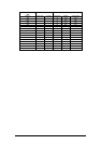
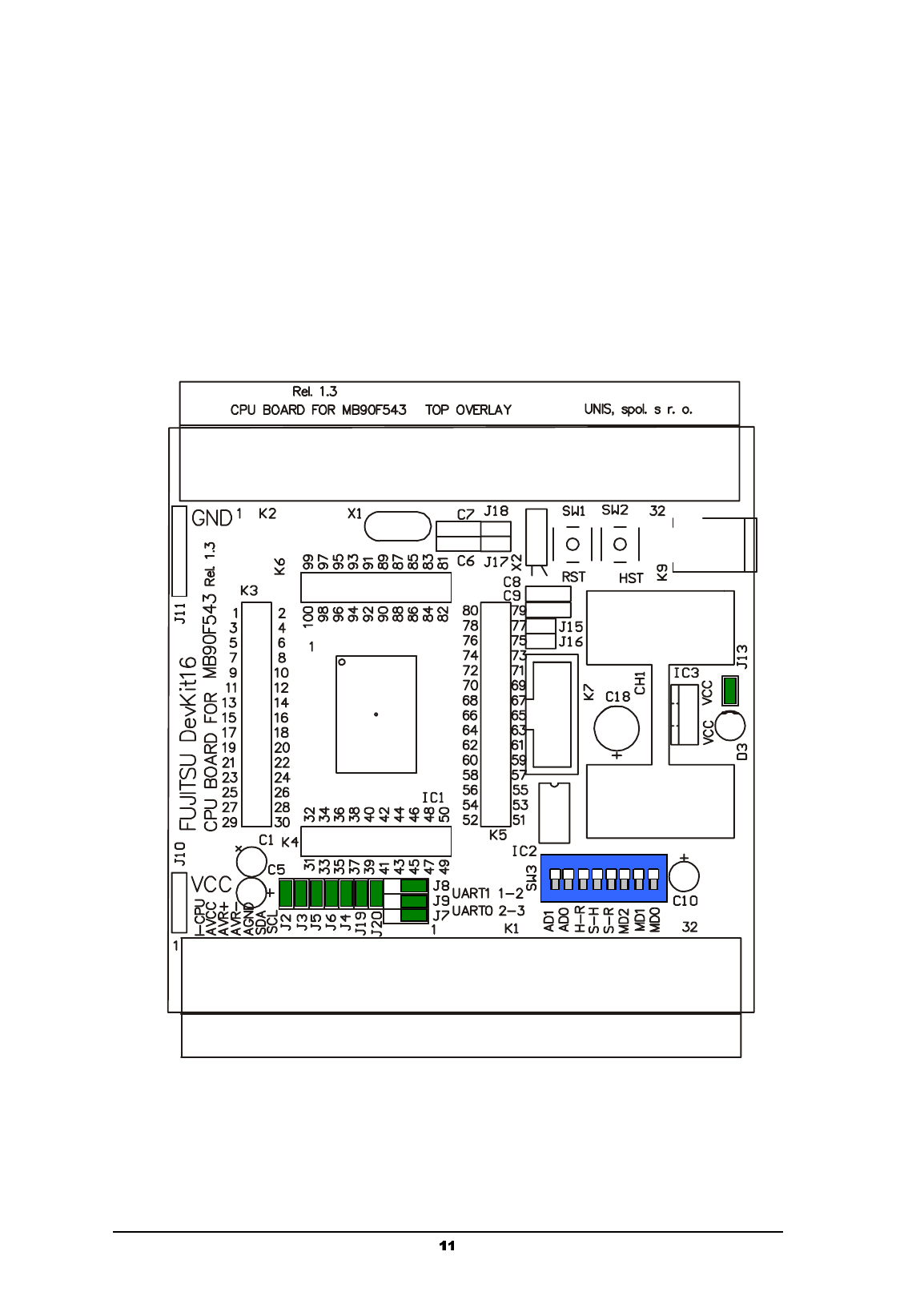
Figure 1: CPU board layout and default jumper settings
8 7 6 5 4 3 2 1
O
O
N
N