


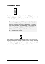
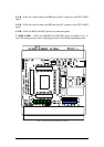
The serial interface connector should be used only when the CPU board is not connected
to the mainboard, because mainboard connects its own serial (RS232) interface to the
UART0 and UART1 CPU signals. To be able to use the K7 connector, please refer to the
description of J7, J8, J9 jumpers later in this section.
Warning: if you want to use the K7 connector when Mainboard is
connected to the CPU board, you have to disconnect the serial interface
selected by J7-J9 from the RS232 drivers on the Mainboard. To achieve this,
remove jumpers on positions 3-4, 5-6 from both the J21 and J22 headers on
the Mainboard. Also, when the Async. Serial programming mode is set on
the Mainboard System control DIP switches, the FPGA UART RS232 driver
is connected to UART0 or UART1 (depending on the setting of the
UART0/1 switch) after reset. If you want to use K7 also in that case, remove
the 3-4, 5-6 jumpers on the J23 as well.
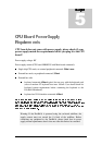
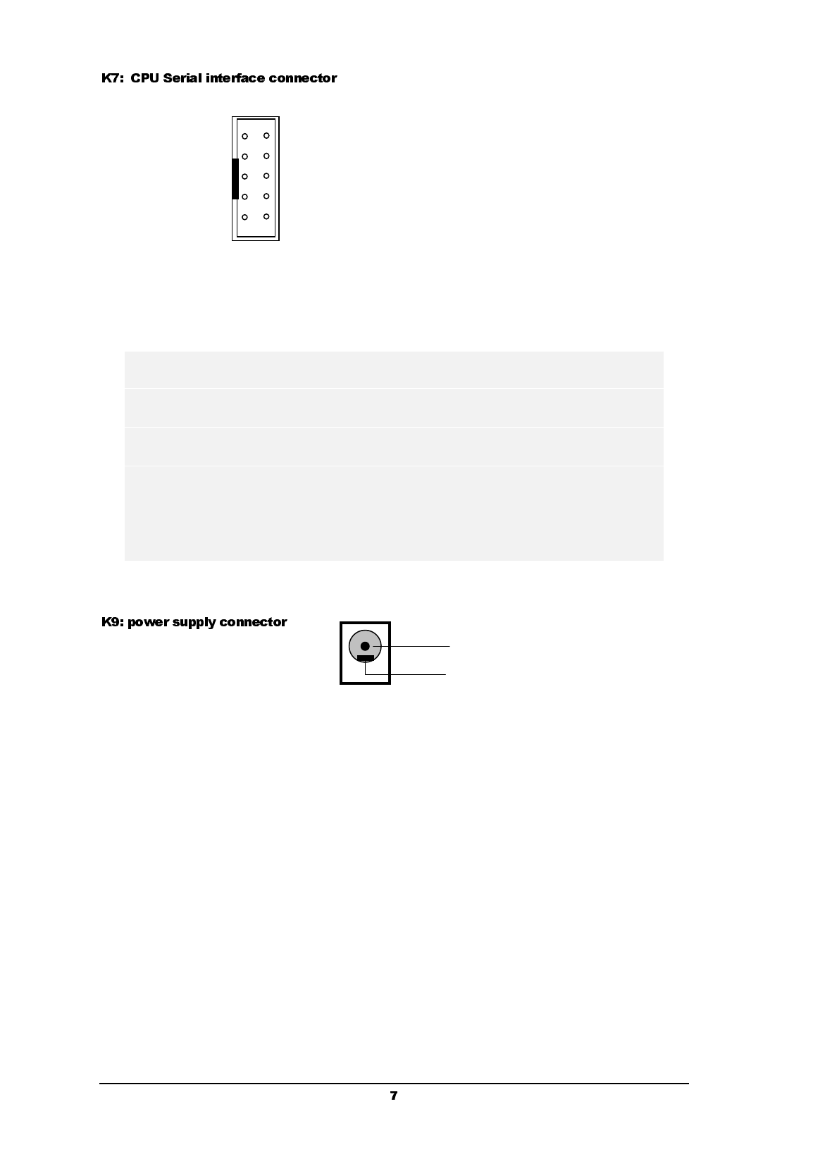
Before applying the power to the Devkit16, check the polarity of your power chord plug –
the GND must be in the center, while the +9V on the shell of the connector. Even thought
the DevKit16 power lines are protected by a diode on the power input, do not ever apply
power with the opposite polarity. Also, make sure that the power supply complies to the
specifications in chapter CPU board Power Supply Requirements.
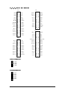
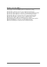
AD00 1
MD0 3
SERRES 5
SOT 7
VCC 9
2 AD01
4 MD2
6 SIN
8 SCK
10 GND
GND
+9V