


2-2
2.2 Block Diagram
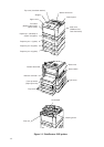
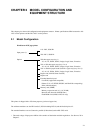
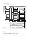
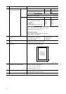
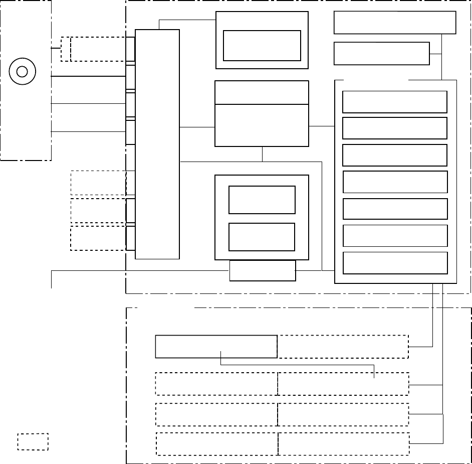
Figure 2.1 shows a block diagram of the PrintPartner 20W printers.
Mechanism controller
Control panel
Switches, LEDs, and
display (LCD)
Control panel interface
Video
inter-
face
DC supply
Main
controller
Interface
control
circuit
Multi-function feeder
Drive
circuit
Sensors (cover-open, etc.)
Printing mechanism
Motors
Halogen lamp (fuser)
High-voltage
power supply
Low-voltage
power supply
Double-sided print mechanism
Power-supply unit
Printer mechanism
First paper tray
Duplex (double-sided print) unit
Second feeder unit
First feeder unit (with paper tray)
Third feeder unit
Second feeder unit (with paper tray)
AC cable
AC power
supply
: Option
Simplex configuration
Duplex configuration
Paper feeders
➛
➛
➛
➛
➛
Fourth feeder unit
Third feeder unit (with paper tray)
➛
➛
Moved for duplex
➛
➛
➛
Emulation or
font card
Extended
RAM card
Extended
RAM card
Extended
interface board
Parallel interface
(Centro type B)
Parallel interface
(Centro type C)
Serial interface
(RS232C, 9-pin)
CPU
PrintPartner
Software
CD-ROM
Printer driver
MarkVision
PPMENU
Face-down stacker
Face--up stacker
Multifunction feeder
Figure 2.1 Printer block diagram
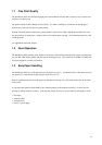
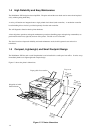
(1) Printer
The printer consists of a main controller, a control panel, a printer mechanism, a mechanism controller, paper
feeding mechanisms including paper feeders, a power supply, and covers.
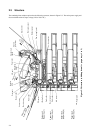
The printing mechanism consists of a laser unit, a print unit (photoconductive drum, developing magnet roller,
precharger), a toner bottle, a transfer charger, and a fuser unit.