


8
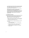
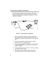
3.2 Microfilter Installation Procedures
Installing m icrofilters should not require any new inside
wiring. Existing wired RJ-11 telephone jacks are all that is
required to comp lete thi s installation. See Figure 3-1 for an
installation diagram.
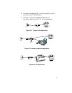
1. Start in the l ocation w here you want to install your
DSL modem. L ook for the existing phone outl et (RJ-11
faceplate), and remove the existing RJ-11 cord from the
wall.
2. Connect the provided two-outlet modular a dapter
device into the RJ-11 telephone jack.
3. Connect the provided D SL modem RJ-11 line c ord, part
number FC9660CB26, into one side of the two-outlet
modular adapter.
4. Connect the other end into the RJ-11 L INE slot, located
on the back of DSL modem.
5. Connect one of the provided microfilters into the
remaining em pty two-outlet m odular adapter slot.
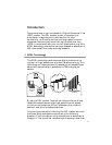
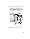
Figure 3-1: Typical Splitterless Installation
m1227.fh8_4
RJ-11
Phone
Jack
Microfilter
Telephone
DSL Modem
FC9660RA12
2-Outlet
Modular
Adapter
LINE
PHONE
Line
RJ-11 Line Cord
FC9660CB26
POWERMODEM DATA
DATA
DATA
LINE
LINE